Please login with a confirmed email address before reporting spam
Posted:
7 years ago
2016年10月25日 GMT-4 22:47
The answer is actually in the documentation, which I'd applied to the cylinder, but not to the end caps.
Instead of using a self-closing surface, partition it into two half-surfaces:
x = s1 ⨉ L
y = R ⨉ sin(π s2)
z = R ⨉ [ (1 + α)/2 + ½ (1 – α) cos(2π s1)] cos(π s2)
and
x = s1 ⨉ L
y = R ⨉ sin(–π s2)
z = R ⨉ [ (1 + α)/2 + ½ (1 – α) cos(2π s1)] cos(–π s2)
The end-caps are then semi-circles:
x = 0
y = R ⨉ s1 ⨉ cos(π s2)
z = R ⨉ s1 ⨉ sin(π s2)
x = 0
y = R ⨉ s1 ⨉ cos(–π s2)
z = R ⨉ s1 ⨉ sin(–π s2)
and semiellipses:
x = L
y = R ⨉ s1 ⨉ cos(π s2)
z = R ⨉ α ⨉ s1 ⨉ sin(π s2)
x = L
y = R ⨉ s1 ⨉ cos(–π s2)
z = R ⨉ α ⨉ s1 ⨉ sin(–π s2)
When I use these as the elements for "convert to solid" I get what I want.
Jeff Hiller
COMSOL Employee
Please login with a confirmed email address before reporting spam
Posted:
7 years ago
2016年10月26日 GMT-4 09:05
Hello Daniel,
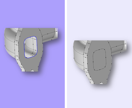
An alternative approach is to use the "Cap Faces" capability. One benefit of it is that it applies even when there is no known analytical expression for the end caps.
A simple example taken from the CAD Import Module webpage is here:
cdn.comsol.com/products/cadimport/capping_550x450_color.png
That image does not really do "Cap Faces" justice since the capping face is planar and "boring"; like I said above, this can be used even if the end cap does not have a known analytical form.
"Cap Faces" is one of the advanced geometry operations that come with the CAD Import Module, Design Module and LiveLink for CAD products.
Best,
Jeff
Hello Daniel,
An alternative approach is to use the "Cap Faces" capability. One benefit of it is that it applies even when there is no known analytical expression for the end caps.
A simple example taken from the CAD Import Module webpage is here:
https://cdn.comsol.com/products/cadimport/capping_550x450_color.png
That image does not really do "Cap Faces" justice since the capping face is planar and "boring"; like I said above, this can be used even if the end cap does not have a known analytical form.
"Cap Faces" is one of the advanced geometry operations that come with the CAD Import Module, Design Module and LiveLink for CAD products.
Best,
Jeff
Please login with a confirmed email address before reporting spam
Posted:
7 years ago
2016年10月26日 GMT-4 12:27
Thanks, Jeff! Coming up with analytic representations of smooth surfaces is part of the fun, but your suggestion is an excellent one, and motivates an expansion of our set of our license set here.
One issue: the structure I have consists of six surfaces and one conversion operation with a structure defined by essentially 3 parameters. It seems to me to be a natural application for a macro specification: provide the macro with the three parameters, automatically get the given structure. I am reminded of POV-Ray, a ray-tracer which has geometric primitives controlled with a simple text language, where such macros are possible, and almost essential for the construction of non-trivial scenes. The structure I'm simulating (for fun and learning, not directly for research) would use this macro-object 4 times, although better would be two instances of macros which each use the macro-object twice. So is there a recommended approach to this without abandoning the GUI in favor of Matlab, which is a direction I'd prefer to not go?
Jeff Hiller
COMSOL Employee
Please login with a confirmed email address before reporting spam
Posted:
7 years ago
2016年10月26日 GMT-4 13:30
If I catch your drift you're talking about what COMSOL calls "Geometry Parts" (Formerly "Geometry subsequences"). More info on that concept is available here:
www.comsol.com/release/5.1/mesh-and-geometry
Check out also the file at the link below for an example where I used the concept to rapidly draw a bunch of dominoes.
-------------------------------------------
cds.comsol.com/mg/b5810e700585bd.zip
Estimated size: 3.7 MB
This link expires November 2, 2016. Please make sure to download before that date.
Included files:
- 5p2_Domino_Small.mph
-------------------------------------------
Best,
Jeff
If I catch your drift you're talking about what COMSOL calls "Geometry Parts" (Formerly "Geometry subsequences"). More info on that concept is available here: https://www.comsol.com/release/5.1/mesh-and-geometry
Check out also the file at the link below for an example where I used the concept to rapidly draw a bunch of dominoes.
-------------------------------------------
http://cds.comsol.com/mg/b5810e700585bd.zip
Estimated size: 3.7 MB
This link expires November 2, 2016. Please make sure to download before that date.
Included files:
- 5p2_Domino_Small.mph
-------------------------------------------
Best,
Jeff
Please login with a confirmed email address before reporting spam
Posted:
7 years ago
2016年10月26日 GMT-4 16:03
Thanks! Here's my object, which was implemented with a 2nd-order continuous function implemented with an "if" function on the parametric surfaces (top and bottom), with 4 more parametric surfaces for the two end-caps.
i.imgur.com/3lmzd2J.png
Thanks! Here's my object, which was implemented with a 2nd-order continuous function implemented with an "if" function on the parametric surfaces (top and bottom), with 4 more parametric surfaces for the two end-caps.
http://i.imgur.com/3lmzd2J.png
Please login with a confirmed email address before reporting spam
Posted:
7 years ago
2016年10月26日 GMT-4 16:54
That's fantastic! Although I admit I'm quite disappointed with the scope of the implementation. I was expecting something more in the time-dependent structural mechanics realm, perhaps exercising the contact model with friction, for example something like:
www.youtube.com/watch?v=ARM42-eorzE
although this would also have required modeling rolls of duct tape.
That's fantastic! Although I admit I'm quite disappointed with the scope of the implementation. I was expecting something more in the time-dependent structural mechanics realm, perhaps exercising the contact model with friction, for example something like:
https://www.youtube.com/watch?v=ARM42-eorzE
although this would also have required modeling rolls of duct tape.
Jeff Hiller
COMSOL Employee
Please login with a confirmed email address before reporting spam
Posted:
7 years ago
2016年10月26日 GMT-4 18:07
:) I'll get right on it.
Jeff
:) I'll get right on it.
Jeff
Please login with a confirmed email address before reporting spam
Posted:
7 years ago
2016年10月27日 GMT-4 19:12
While you're working on that, I've been doing something similarly relevant. The analytic solids are the two tapered top sections, tapering from circular cross-section to eccentric cross-section. This is investigating the impact of an isoareal eccentric cross-section, designed for aerodynamics, on stiffness. The whole thing is hollow with a 1.3 mm wall thickness (except in the eccentric section where the wall thickness is non-uniform), the result of liberal use of boolean differences.
i.imgur.com/axqSPPn.png
While you're working on that, I've been doing something similarly relevant. The analytic solids are the two tapered top sections, tapering from circular cross-section to eccentric cross-section. This is investigating the impact of an isoareal eccentric cross-section, designed for aerodynamics, on stiffness. The whole thing is hollow with a 1.3 mm wall thickness (except in the eccentric section where the wall thickness is non-uniform), the result of liberal use of boolean differences.
http://i.imgur.com/axqSPPn.png
Jeff Hiller
COMSOL Employee
Please login with a confirmed email address before reporting spam
Posted:
7 years ago
2016年10月28日 GMT-4 08:41
You might like this app:
https://www.comsol.com/model/bike-frame-analyzer-35101
Jeff

