Flow and heat transfer simulations as a development tool for a novel microcalorimeter
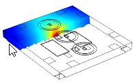
Calorimetry is the method of choice for determining one of the most elementary physical quantities: heat, Q [in J]. Depending on the individual issue a wide range of techniques, devices and methods are available for users [1]. One approach is called isothermal microcalorimetry (IMC). It enables real-time heat flow measurements in the µW (µJ·s-1) range. Experiments are performed in an isothermal operation mode. It means that the operating temperature is kept constant with a variance of some hundred µK. The physical, chemical or biological process of interest generates heat which is transferred from the reaction chamber to a heat sink via a thermoelectric generator (TEG, i.e. Peltier elements) [2]. The TEG generates a voltage that is proportional to the heat released by the reaction. In general, the composition of such a calorimeter could be roughly divided into four essential elements: i) the sample which undergoes any physical, chemical or biological reaction that releases or consumes heat, ii) the measurement unit that recognizes these heat changes, iii) the heat sink that ensures a constant temperature on one side of the heat flow sensor and finally iv) the temperature control system which precisely regulates the surrounding as well as the temperature of the heat sink. For the accuracy and sensitivity of such a calorimetric device, it is crucial to tightly control and quantify all heat flow paths from the reaction chamber to the surrounding. In our study, we performed flow and heat transfer simulations of a simplified 3D-test model of the developed microcalorimeter. The 3D model has two main parts: an outer zone containing an interior fan heater that distributes as well as heats the air and an inner zone. That inner zone is composed of the measuring chamber as well as the heat flow sensor unit (TEG) and a massive aluminium heat sink. The temperature of the heat sink is controlled by two thermoelectric coolers and two heating films. The latter acts as a preheating component to quickly heat the device to the set operating temperature during start-up. This multiphysics problem is simulated by the non-isothermal interface which connects the laminar flow and heat transfer physics. Additionally, two event interfaces are used. One, to turn off the preheating function of the heating films after reaching the desired set-point temperature. The second to regulate the surrounding air temperature via an on-off control mechanism of the interior fan heater. The power to both thermoelectric coolers is regulated by a PID controller. Performing these simulations gives us an extensive view inside the calorimeter especially of the temperature distribution on the heat sink. The results obtained greatly aided us in the devices construction process and provide us with valuable information about the overall system performance. Finally, to verify our simulation we compared those results with experimental data obtained from the actual calorimeter prototype.
Keywords: Microcalorimetry, CFD and HT simulation, thermal engineering, temperature distribution [1] Russel M, Yao J, Chen H, Wang F, Zhou Y, M F Choi M et al. Different Technique of Microcalorimetry and Their Applications to Environmental Sciences: A Review. Journal of American Science. 2009;5(4):194-208.
[2] Wadso I, Goldberg RN. Standards in isothermal microcalorimetry (IUPAC technical report). Pure Applied Chemistry. 2001;73(10):1625-39