Microwave Exposure System for In Vitro and In Vivo Studies
A computer controlled microwave exposure system and specialized applicators were constructed for the purpose of facilitating accurate observations of microwave radiation effects on uninfected and infected biological tissue in vitro and in vivo under different electromagnetic modalities and exposure configuration. To address diverse requirements, three different applicators were developed: a broadband TEM chamber for either in vivo or in vitro, a narrowband TE101 waveguide and PTFE sample holder resonant at 2.45 GHz only for standing wave in vitro, and an innovative broadband quasi-TEM microstrip device for irradiating microscope slide mounted samples with high microwave fields simultaneously as they are being studied under a microscope (our so-called M3 fixture).
In support of these new applicator designs, modeling was done using COMSOL Multiphysics® software. For in vivo modeling of mice in the TEM chamber applicator, the 3D Digimouse [1] image and tissue atlas defined tissue properties (permittivity, loss tangent, density, heat capacity, etc…) at 100 um voxel resolution. This was done using LiveLink™ for MATLAB®. As shown in Figure 1, the mouse was placed on and under perfectly conducting surfaces spaced and driven as the septum and floor of the TEM cell. Perfectly Matched Layer (PML) absorbing boundaries were used around the edges. Given the posture of the animal in the Digimouse data, the HKE orientation (Nose pointing in H-field direction; dorsal side in E-field direction) was considered exclusively.
The cavity and M3 applicators for blood irradiation experiments were also modeled extensively. Dual physics microwave heating studies were conducted, exploring SAR and heating of alternative holder configurations for 200 ul sample tubes. Predicted S11 of the cavity and M3, as well as thermal effects in the sample were verified empirically.
Modeling of the cavity applicator showed problematic non-uniformity of the electric field within the sample. Figure 2 is a simulation of the cavity applicator with 3 watt incident SAR (W/kg) at four horizontal cuts through microcentrifuge tube. The front-back, and tube-tip non-uniformity of exposure is evident. Based on the COMSOL results, an improved PTFE holder was developed to allow inverted sample tubes. This holder reduced the SAR nonuniformity and improved cooling to reduced temperature rise.
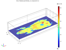
The COMSOL simulation showed the steady state temperature distribution in the M3 applicator after RF exposure. The simulated thermal map matches well with direct observation using thermochromic pigment as seen in Figure 3. Another fact revealed by the modeling of the M3 applicator is that for relatively lossy tissue (e.g. blood) the peak E-field occurs along the edges of the strip, in full view, as shown in Figure 4. Under the strip, the wave is mostly H-field.
This new system will allow experimental observation of microwave radiation effects on biological tissues, pathogens, and other micro or nano scale structures in a variety of modalities. The use of COMSOL simulations was essential to the design and development of the microwave applicators.
下载
- nadovich_paper.pdf - 2.36MB
- nadovich_abstract.pdf - 0.25MB