How to Partition and Split Geometry into Separate Parts
The COMSOL Multiphysics® software includes split and partition operations that enable you to divide and separate any part of your model geometry. In this article, we will go over how to divide a model geometry to create separate regions.
Use Cases and Functionality
The functionality for subdividing your model geometry is useful in many cases, such as when you want to:
- Split geometric entities, like objects, domains, boundaries, and edges
- Remove parts of the geometry in your model — this can be done to simplify your model or clean up the geometry in preparation for modeling
- Improve the meshing of your model geometry, like when working with geometry that is complex or has parts exhibiting a high aspect ratio
- Introduce an interior boundary, such as when motivated to do so for defining the physics or other aspects of the model setup
You can split your model geometry with partition operations by using a work plane to produce the cut.
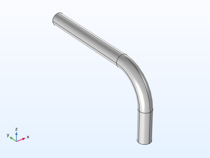 A 3D pipe bend model.
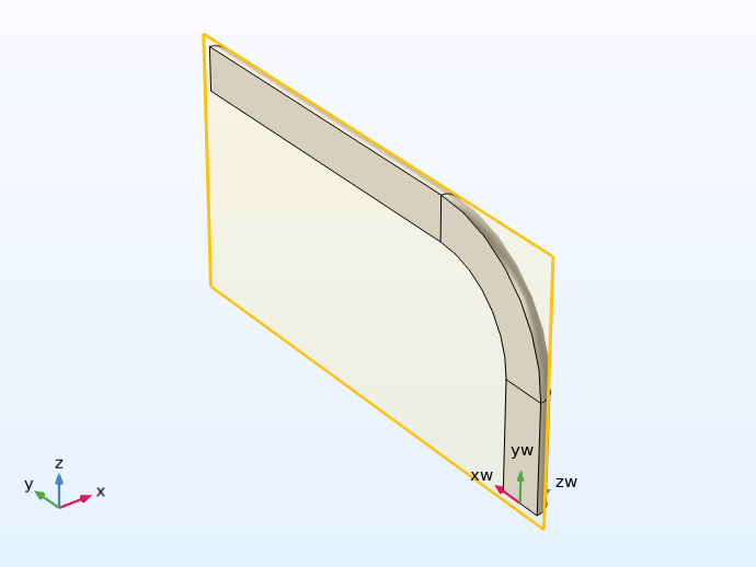 Half of the pipe bend model, showing the partition work plane.
The geometry for a model of a pipe bend (left), which is partitioned in order to remove half of the geometry (right), showing its symmetry. A work plane is used to execute the partition.
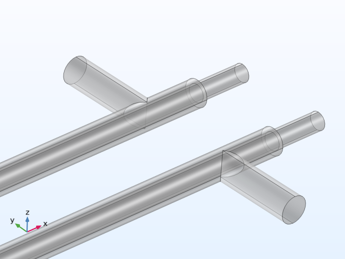 A 3D double pipe heat exchanger model.
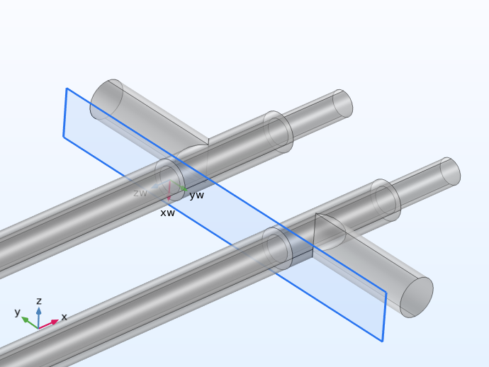 The 3D double pipe heat exchanger model with the work plane showing separated sections of the geometry.
The model geometry for a double pipe heat exchanger is partitioned in order to use different types of meshing for each region. A work plane is used to execute the partition.
You can also build so-called tool objects, which are geometric objects that can be used in the partition operation to create separate regions of your model geometry. This is the sole purpose of these objects.
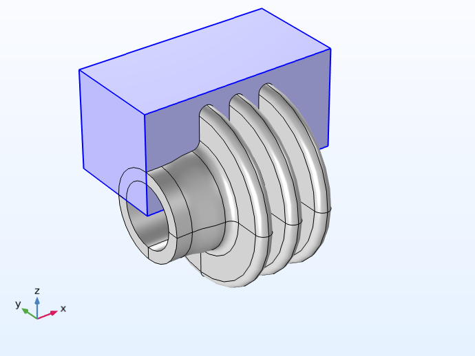 A flange model with a rectangular tool object used to separate areas of the geometry.
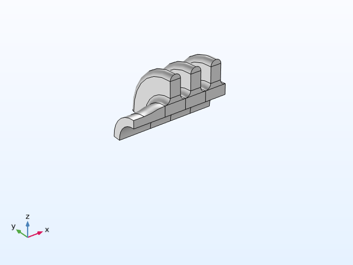 The flange model partitioned to a quarter of the geometry, with the section previously highlighted by the tool object as the remaining part.
The model geometry for a flange is partitioned using a block as the tool object (left) in order to reduce the flange to a quarter (right).
Additionally, you can split a geometry into its corresponding entities by using a Split operation. This enables you to split any composite object into multiple objects, which you can then perform geometric operations on individually.
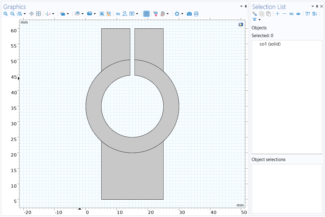 One of the cross sections drawn for the feeder clamp tutorial model geometry. Before the Split operation is used, the geometry consists of one geometric object.
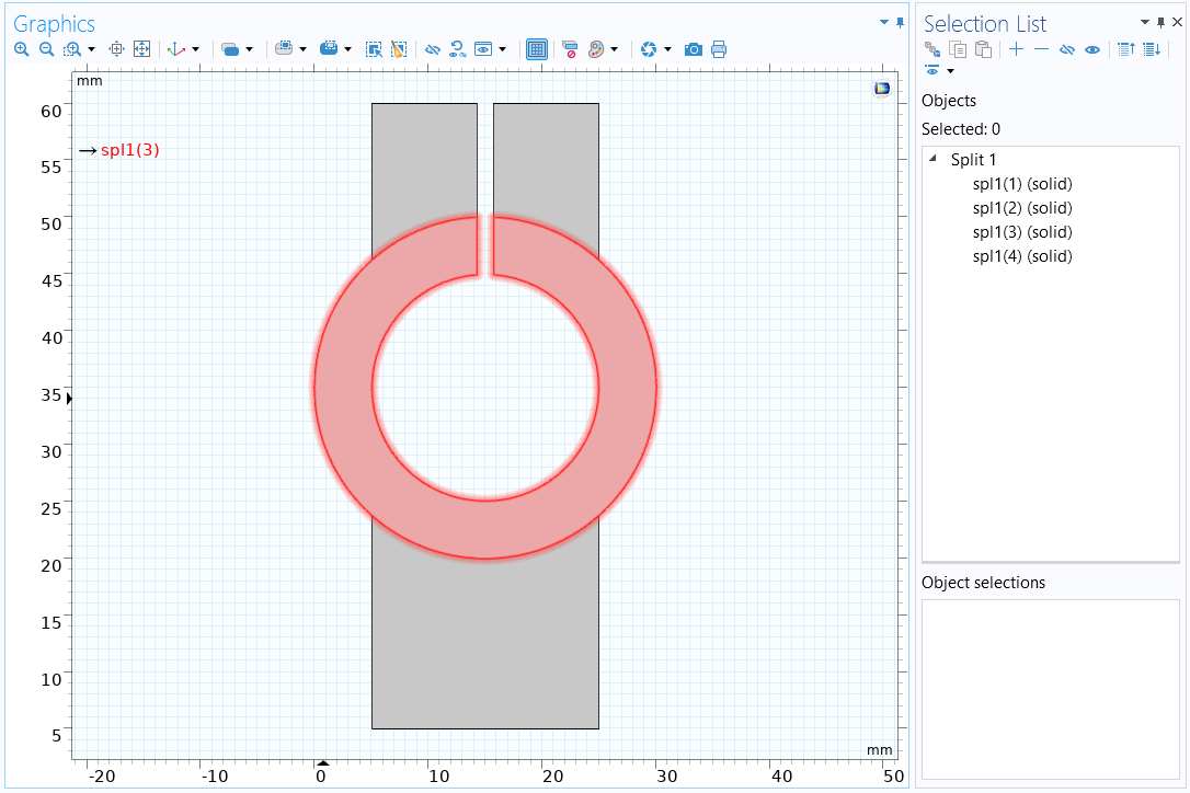 Upon using the Split operation, the formerly single geometric object is split into four geometric objects, one of which is highlighted in red. For this model, splitting the object into its entities enables us to separately extrude each region of the cross section to a different length.
You can also extract lower-level geometric entities from geometry objects to make new objects using the Extract operation. For example, you can extract a surface from a 3D solid, making it a new surface object. In some cases, this operation will be more suitable than the Split operation, as you can remove the input objects after extracting the geometric entities desired.
Process of Splitting Geometries
Splitting the geometry of your model into separate entities only requires adding a Split operation and selecting and applying it to the geometric object(s) in your model geometry that you want to partition (as demonstrated in the video above).
Creating separations in any part(s) of your model geometry via the partition operations is done in three steps:
- Add the work plane or build the tool object
- Add the partition operation
- Subdivide the geometry
You can separate geometry objects, domains, boundaries, and edges using the respective partition operation. The options available will depend on the spatial dimension you are working in. Follow along and learn by opening the software using the reference file and watching the video below as we show you how to partition a geometry in the software. We also discuss the advantages of using the partition functionality to simplify or reduce your model, such as how it can reduce the computational resources needed to compute a model.
Tutorial Video: How to Partition Geometry
Modeling Exercises
Practice what you have learned here with the modeling exercises listed below. The directions are generalized to encourage self-guided problem solving. Once you are finished, you can check your implementation by referencing the solution model files provided here or use the comparison tool to identify the differences between the models.
Recommended exercises:
- Partition the pipe bend model geometry so that you are modeling half of the pipe (MPH-file)
- Partition the double pipe heat exchanger geometry so that two splits are introduced 0.4 m and 6 m from the pipe inlet/outlet (MPHBIN-file)
- Partition the flange geometry so that you are modeling a quarter of the flange (MPHBIN-file)
- Separate the geometry for a convex lens into individual entities so that each can be moved to the same plane (MPHBIN-file)
For the pipe elbow model geometry listed here, you can download the MPH-file from the linked text. For the MPHBIN files, download the files linked above and then import them into a component by choosing Import under the Home or Geometry ribbon tabs or from the menu that pops up after right-clicking the Geometry node.
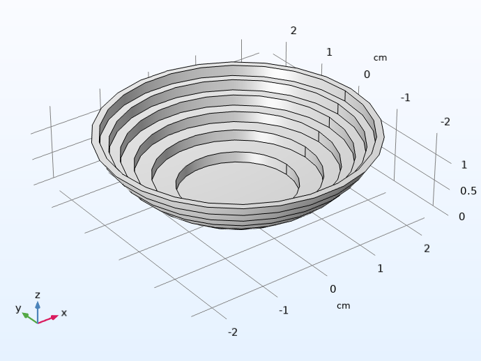 The full 3D convex lens model.
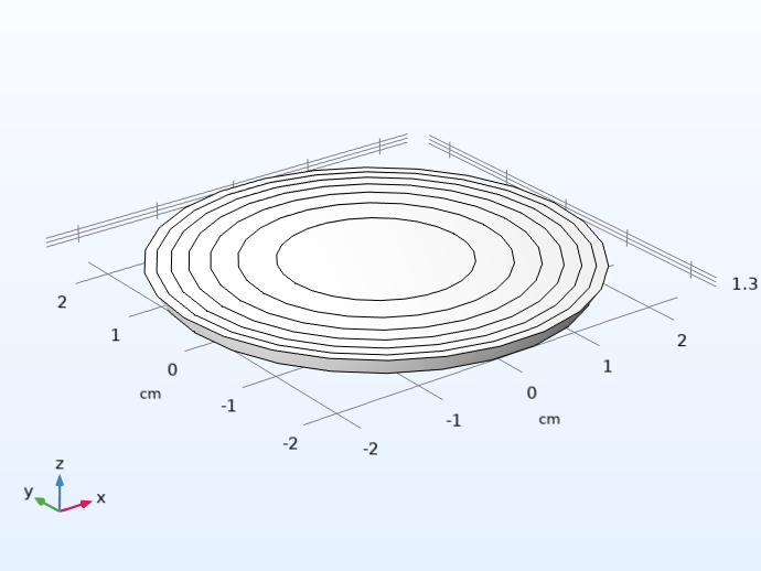 The partitioned convex lens model.
The example geometry for a convex lens (left) is split into individual entities, which are then moved to the same plane to form a Fresnel lens (right).
Further Learning
There are several tutorial models available that utilize partition and split operations. To find these, you can search @geom:par or @geom:spl in the Application Libraries. You can also check out our blog post "Improving Your Meshing with Partitioning" to learn about how the partition operations can make meshing more efficient.
请提交与此页面相关的反馈,或点击此处联系技术支持。