Manually Setting Up the Geometric Multigrid Solver
Overview
The geometric multigrid (GMG) solver accelerates the convergence of the iterative solver by solving the finite element problem on a series of meshes rather than a single one. The multigrid algorithm starts with the initial physics-controlled mesh or user-defined mesh and automatically builds a series of coarser meshes.
Each additional mesh is approximately twice as coarse as the previous one. The total number of meshes depends on the size of the model. Multigrid meshes are automatically built by the solver until the coarsest mesh leads to a low enough number of degrees of freedom to be solved with a direct solver.
While building the multigrid levels, the mesh size on the coarsest meshes might become larger than the size of the model’s smallest geometrical features. This is typically the case when the geometry includes small features or parts with a high aspect ratio. There are some different approaches that we can use to address this, which we discuss below.
Resolving Models with Complex Geometries Using the GMG Solver
Different strategies can be used to resolve large models containing complex geometries with the iterative multigrid solver. To illustrate them, we consider the example model geometry pictured below.

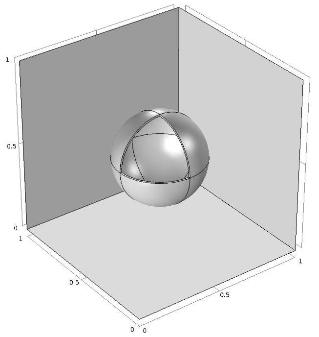
An example model geometry wherein a manual setup for the GMG solver is demonstrated. The geometry consists of a block containing a sphere that has a thin outermost layer.
This cube, made of one material, includes a sphere made of a second material and is coated with a thin layer of a third material. The thickness of this layer is much smaller than the size of the sphere, which would cause the multigrid solver to fail. Regardless of the type of geometry you are working with and the features contained therein, there are ways we can resolve this issue when encountered and proceed with using the GMG solver.
Approach 1: Replace Multigrid Meshes that Failed with User-Defined Meshes
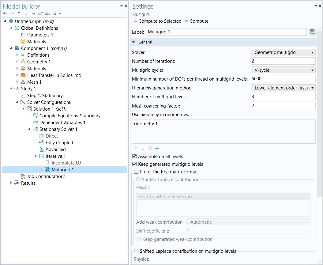
Rather than letting the mesher automatically build coarser meshes from the initial mesh, manually build and replace the meshes that failed with user-defined meshing sequences. Then, select these meshes within the multigrid solver settings. The number of multigrid levels required to solve the model discussed in this article can be seen in the Settings window below for the Multigrid 1 node.

The settings for the multigrid solver node used to set up a GMG solver.
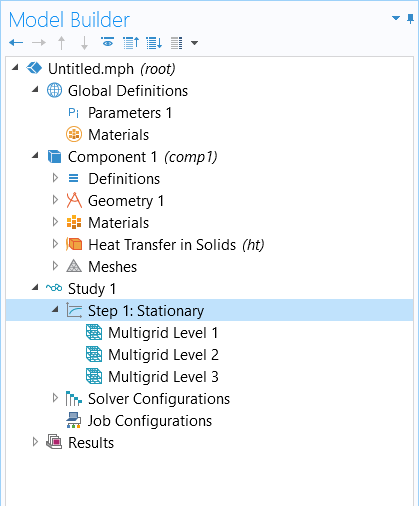
In this example, three additional meshes are required, as seen in the Number of multigrid levels field. After clicking the Compute button, the solver returns the error message: "Problem setting up multigrid". To visualize the multigrid meshes and see how many of them failed, we can select the Keep generated multigrid levels check box in the settings for the Multigrid 1 node (pictured above). After recomputing the solution, the multigrid levels are added as subfeatures to the study step node Step 1: Stationary.

The multigrid levels added under the Stationary study step after the model is recomputed.
If you are unable to see the multigrid levels that populated under the study step node, you may need to toggle on the advanced study options available in the software. To enable viewing these nodes, you can use the Show button in the Model Builder toolbar and select the Multigrid Level check box under the Study category.
The corresponding coarser meshes will appear in the model tree. Mesh 1 is the original mesh. Meshes 2 through 4 represent the multigrid levels 1 to 3, respectively. As seen in the below snapshots, Mesh 4 fails because it is too coarse to discretize the geometry.
In order to fix Mesh 4, we can follow one of these procedures:
- Build the meshing sequence for Mesh 4 manually using a finer mesh or a swept mesh
- Add a new coarse mesh, Mesh 5, and change the settings in Multigrid Level 3 from Mesh 4 to Mesh 5
- Delete the coarsest mesh, Mesh 4, and the corresponding Multigrid Level 3 node under Step 1: Stationary to reduce the number of multigrid levels
Note: You need to switch the Hierarchy generation method on the multigrid solver to Manual for selecting the multigrid levels to consider. If Keep generated multigrid levels is checked and if there is no problem when setting up the multigrid levels, the Hierarchy generation method is automatically switched to Manual.
Approach 2: Build All Multigrid Levels Manually
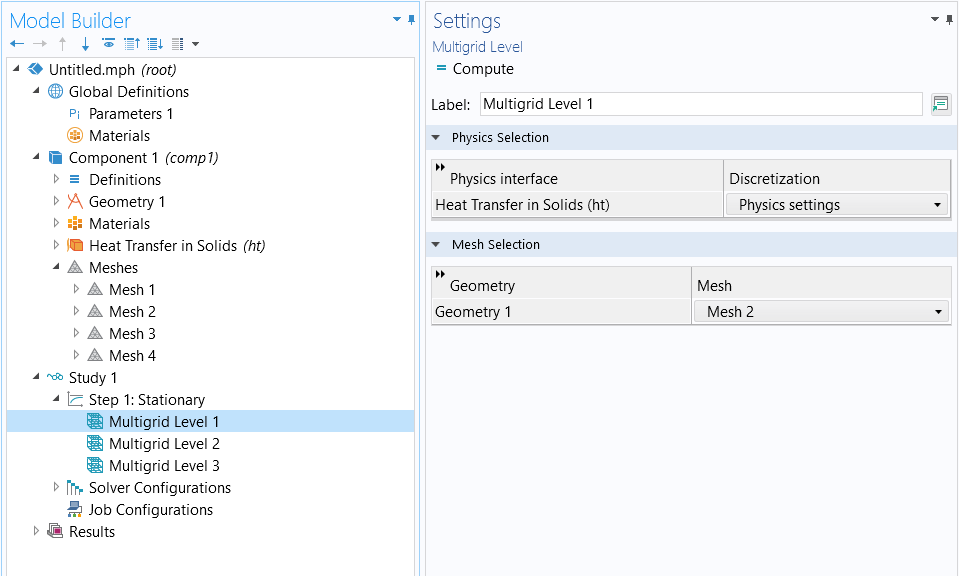
We can build the meshes for each multigrid level manually using user-defined meshing sequences. Each subsequent mesh should be approximately twice as coarse as the previous one. Set the initial mesh to Mesh 1 in Step 1: Stationary and set the additional meshes as multigrid level subfeatures to Step 1: Stationary (Multigrid Level 1 and 3, for instance, should be set to Mesh 2 and 4, respectively.)

Settings window for one of the Multigrid Level nodes, where the geometry and mesh selection to be used is specified.
If the multigrid level subfeature is not available, activate the advanced study options in the Show button in the Model Builder toolbar as discussed earlier in this article. Lastly, in the solver settings, we will want to change the Hierarchy generation method to Manual. Upon switching to Manual, you will see the Settings windows update.
There are a few examples in the Application Libraries where the GMG solver is used, such as the Submodel in a Wheel Rim tutorial model. The model can be found in the software through the Application Libraries (under Structural Mechanics Module > Tutorials) or in the respective Application Gallery entry.
请提交与此页面相关的反馈,或点击此处联系技术支持。

