扫掠网格的术语和要求
在扫掠网格系列课程的第一部分中,我们学习了在哪些情况下可以使用扫掠网格。在第二部分中,我们将深入探讨扫掠 操作的一些细节:扫掠网格的术语,以及何时可以使用扫掠操作。
扫掠网格的术语
首先,我们从介绍 COMSOL Multiphysics® 中有关扫掠网格的一些术语开始。扫掠网格所划分的域上的面被分为源面、目标面或链接面。扫掠操作从源面开始,到目标面结束,以此来定义扫掠方向。链接面连接源面和目标面。
链接边是指与扫描方向近似相切的边或边链。截面边是指近似垂直于扫掠方向的边或边链。
一个截面是由两个截面边包围的面分量。
Note that section faces may include additional isolated faces, such as the small rectangular-shaped face seen in the figure below。
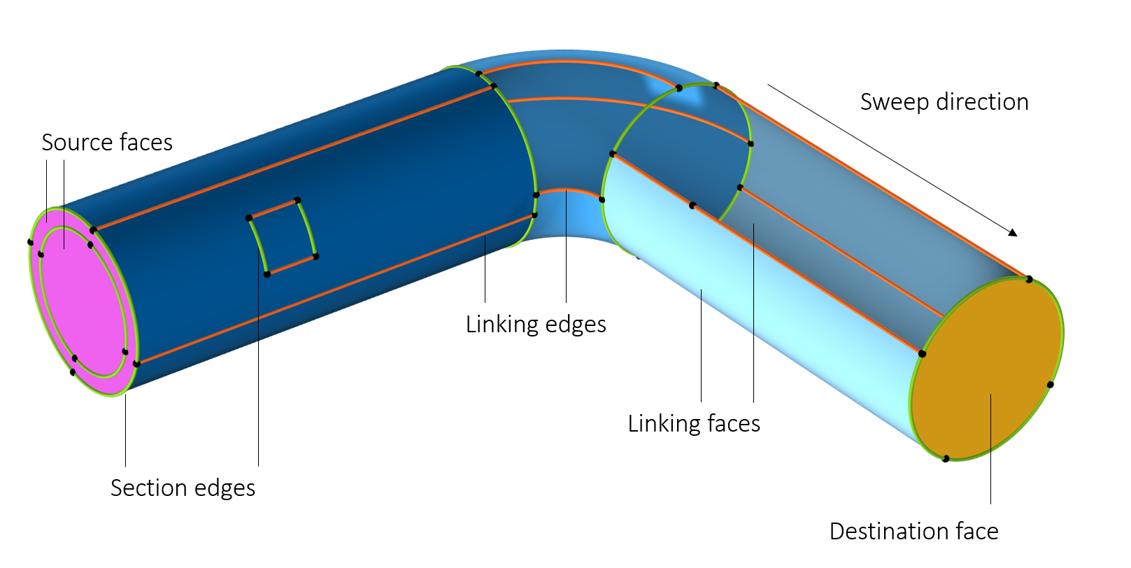
扫掠网格划分的域上的边界和边的分类。截面用三种深浅不同的蓝色表示。隐藏了两个面以显示域的内部。
扫掠网格的要求
在尝试生成扫掠网格之前,第一步是确保目标域符合 此文档中描述的几项标准。由于在几何体中选中扫掠的每个域都遵循相同的逻辑,因此我们将在本课程中重点讨论一个域。这个域符合下述 4 条标准:
- 域中不包含孔、孤立面或空隙
- 源面和目标面必须是连续的面分量
- 每个目标面必须对应一个或多个源面,而每个源面必须精确对应一个目标面或其子集
- 每个截面必须至少有两条连接边或边链
我们将详细探讨上述每一项要求,因为本列表中一些技术性问题被刻意回避了。如果不符合其中任何一项要求,都可能出现错误信息。在后续第三部分课程中,我们将介绍解决这些以及其他潜在问题的技巧。
Since each domain within the geometry selection that will be swept follows the same logic, we will focus on one domain in this part.
对域的形状的要求
处理孔、孤立面和空隙
域中不允许有孔、孤立面或空隙。唯一的例外情况是,孔或孤立面同时穿透源面和目标面,如下图所示。
 Models with domains that include a hole and face that penetrate both the source and destination of the swept mesh.
包含孔和孤立面的域。左图:由于孔和面都穿透了源面和目标面,因此这些域是可扫掠的。请注意,含孤立面的域可以进行网格扫掠,因为其内部边界可以进行网格映射,并遵循扫掠的大致方向。
 Models with domains that can be swept if they are first partitioned.
The domains to the left can be partitioned into smaller domains that are sweepable。
该域有一个穿透源面和目标面的孔,因此可以生成一个扫掠网格。请注意,孔可以沿扫描路径移动并改变大小,网格也会相应变形。
In addition, domains can contain void regions if they have a geometric thickness and a one-to-one mapping between the source and destination entities, as shown in the images below.
 A shell with a void inside.
 The void region show with a clip plane.
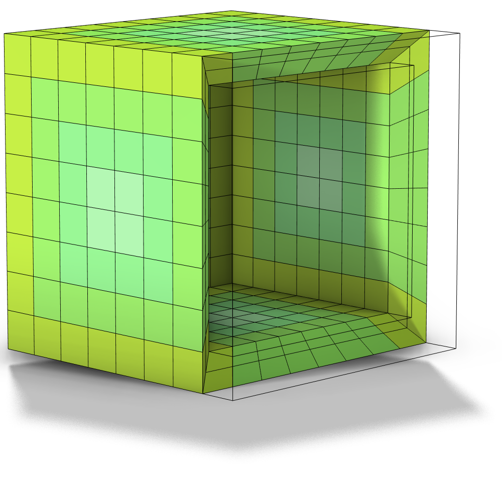 A plot of a swept mesh.
From left to right: 1) A shell domain with a void region inside it. 2) The void region, shown via a clip plane. 3) A plot of a swept mesh. Some elements have been filtered out for visibility.
如何将源面和目标面连接到域
Let's now focus on the second rule. For each domain, the destination must be a connected face component, and, as of version 6.4, the source faces can be disconnected face components. Another way to interpret this rule on a domain level is to say that the domain can contain steps so that the source faces are located on different heights in the sweep direction. For a geometry that contains steps in both ends of the sweep, try to partition the domain into smaller pieces that can be sweepable (as shown in the image of the steel pipe below), or combine a swept mesh with a free tetrahedral mesh.
On a side note, coincident source and destination faces are allowed so long as the source mesh matches the destination (including any twists of the face), as shown in the animation of the torus below.
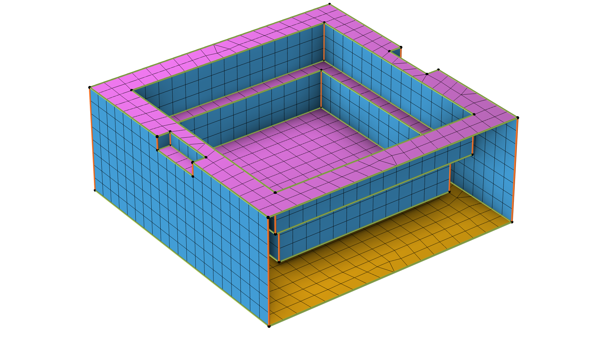 A rectangular 3D geometry with the faces shown with mesh elements.
This domain can be automatically swept meshed as of COMSOL Multiphysics® 6.4. The source faces (magenta) form a disconnected component as they are located on different heights while the bottom surface, the destination face, is a connected face component (yellow).
A rectangular 3D geometry with the faces shown with mesh elements.
This domain can be automatically swept meshed as of COMSOL Multiphysics® 6.4. The source faces (magenta) form a disconnected component as they are located on different heights while the bottom surface, the destination face, is a connected face component (yellow).
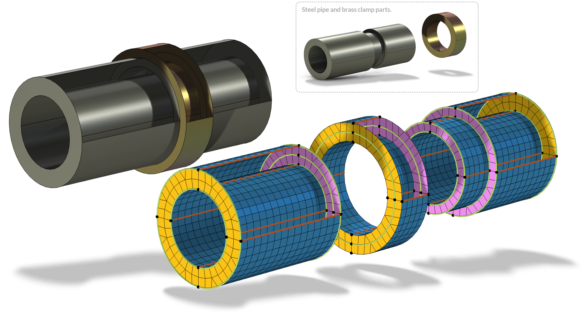 A domain with disconnected face components. A cylindrical 3D geometry is shown assembled, in parts, with the faces colored in yellow, magenta, and blue and mesh elements applied.
The steel pipe to the left is one single domain with an indent where the brass clamp is located. By partitioning the steel domain with a work plane parallel to the side of the clamp, it is possible to sweep a mesh through the whole geometry (exploded view to the right).
A domain with disconnected face components. A cylindrical 3D geometry is shown assembled, in parts, with the faces colored in yellow, magenta, and blue and mesh elements applied.
The steel pipe to the left is one single domain with an indent where the brass clamp is located. By partitioning the steel domain with a work plane parallel to the side of the clamp, it is possible to sweep a mesh through the whole geometry (exploded view to the right).
对扭转环进行的正方形截面网格划分,源的表面网格需要有 180° 的对称性,因为它只转动了半圈。
可视化扫描路径
按照网格的横截面进行扫描,通常有助于形成可视化效果。对前两条标准的解释是,横截面的形状不能有任何突变,similar to what is described in the Source and Destination Faces Requirements section。例如,孔会在横截面上产生空洞,孤立的面会引入新的边,而分岔会在横截面上分割、合并、添加或移除面。虽然这种技术并不是最严谨的,“横截面” 和 “突变” 需要正确定义,但是在大多数情况下,它将有助于定位不可扫掠的域,并为分割域提供线索。See “How to Control the Swept Mesh” for an example of how to partition the geometry in order to sweep parts of it。
直观地解释了之前的域无法进行网格扫略的原因。左边的动画中,横截面被分为两部分。右边的动画中,当到达第一个目标面时,横截面的形状瞬间发生变化。为了直观地演示,在横截面分割的部分显示了部分网格,在该部分如果采用横截面进行分割,可以对域进行网格扫描,但实际上不会生成网格。
可帮助实现上述可视化的一个方法是,添加一个与扫掠横截面平行的剪裁平面 ,然后沿扫掠方向拖动剪裁平面的边框。确保选择显示横截面选项。
这段视频演示了如何从图形窗口手动查看扫掠路径。由于该域包含一个空白域,不符合第一条标准,因此无法扫掠网格。这一点非常明显,因为横截面在扫掠路径的中间部分变成了空心。
孤立实体的特殊示例
孤立边和孤立顶点是指位于域或面内的边和顶点,它们不属于任何一个用于划分面的孤立实体。当存在孤立边和孤立顶点时,网格首先在不考虑孤立实体的情况下生成。然后,第二步,通过移动附近的一些网格节点,将实体包含并黏合到现有网格中。在扫掠过程中,网格与孤立实体保持一致。
If the isolated entities are not needed, consider using Virtual Operations to remove them from the geometry. See this blog post for more information.
 The interior of a mesh with and without isolated entities on the linking faces..
域内无(左)或有(右)孤立实体的内部可视化网格。右图中的网格被扭曲,以便在扫掠过程中考虑孤立的实体。
源面和目标面的要求
每个目标面必须对应一个或多个源面,而每个源面必须精确对应一个目标面或其子集。换句话说,源面可以包含比目标面更多的面,只要有一种方法可以将网格映射到目标面上即可(最多可以有一些变形,就像我们在这个动画中看到的那样)。
 A geometry with more source faces than destination faces.
 A meshed geometry with more source faces than destination faces.
尽管源面(洋红色)多于目标面(黄色),但仍可对该几何体进行扫掠网格划分。
大多数情况下,源面和目标面之间不会发生变形,只需简单地平移和旋转源面,使其与目标面重叠即可。在这种情况下,我们可以在头脑中想象将源网格复制到目标网格,查看复制操作是否可行。下面的动画演示了这种想法的可视化过程。
图中只显示了源面和目标面,颜色与上一个三维视图相同。请注意,源面比目标面多,每个目标面对应一个或多个源面。
不符合此规则的示例:由于目标面较多,因此无法复制网格。网格复制失败的边用红色标出。因此,对于之前的三维几何结构,扫掠方向无法反转。
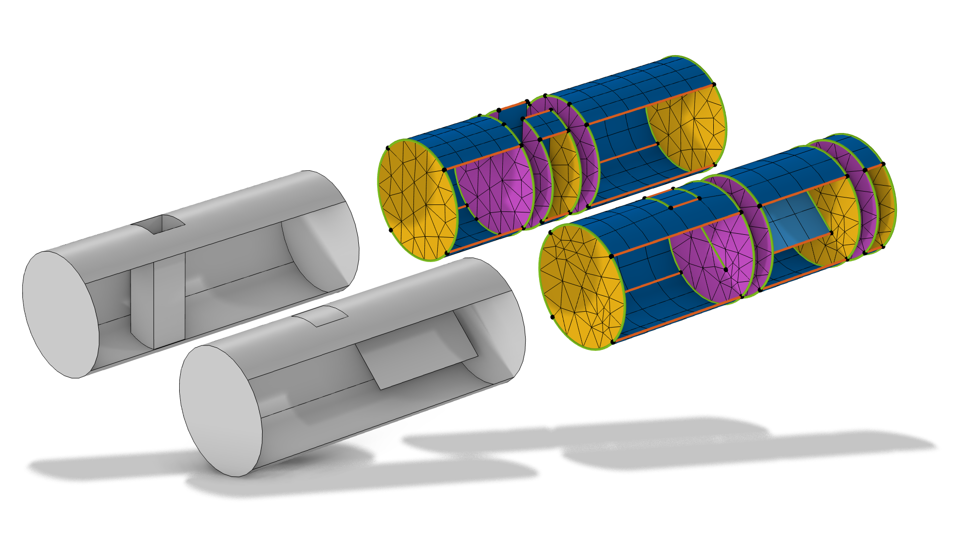
Imprinting some of the edges from the source to the destination, or vice versa, is one strategy to be able to sweep a mesh when there is a mismatch between the source and destination faces in domains or to make sure the sweep creates matching meshes along the sweep. The latter case is shown below.
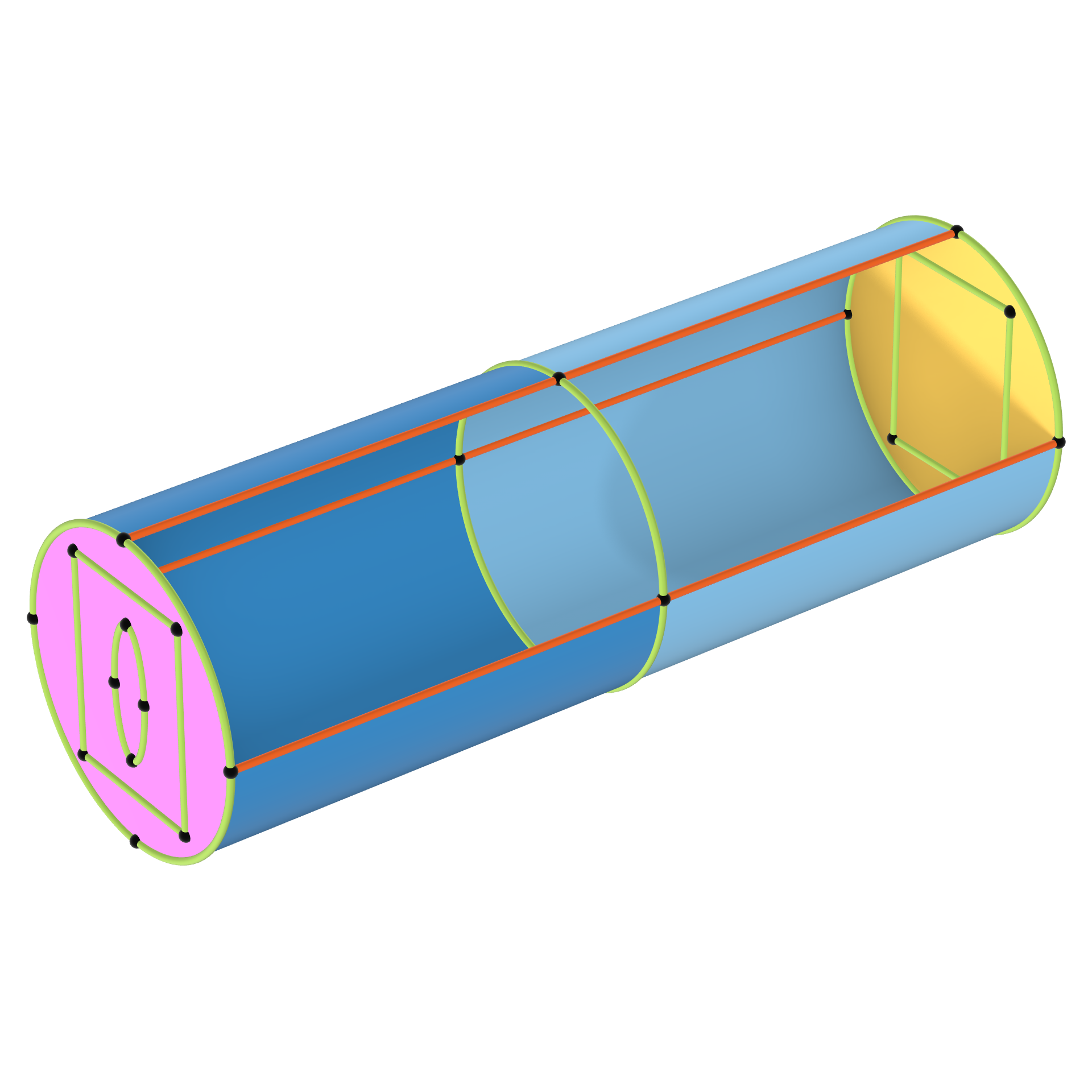
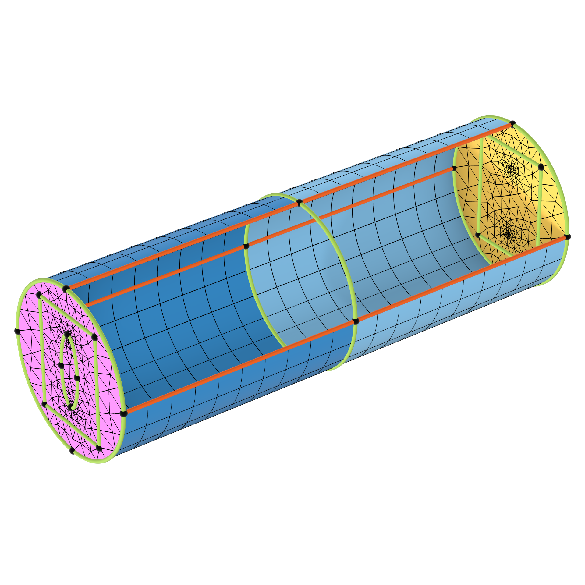
 A cylindrical gray 3D geometry has two domains, which are also shown separately on the right, with the mesh elements and faces colored in magenta, blue, and yellow.
A geometry with two domains where it helps to imprint the rectangle edges on the middle face to make the geometry sweepable. Otherwise, there is no guarantee that the mesh swept from the top to the middle will be the same as for the mesh swept from the bottom to the middle.
A cylindrical gray 3D geometry has two domains, which are also shown separately on the right, with the mesh elements and faces colored in magenta, blue, and yellow.
A geometry with two domains where it helps to imprint the rectangle edges on the middle face to make the geometry sweepable. Otherwise, there is no guarantee that the mesh swept from the top to the middle will be the same as for the mesh swept from the bottom to the middle.
See more examples of imprinting here.
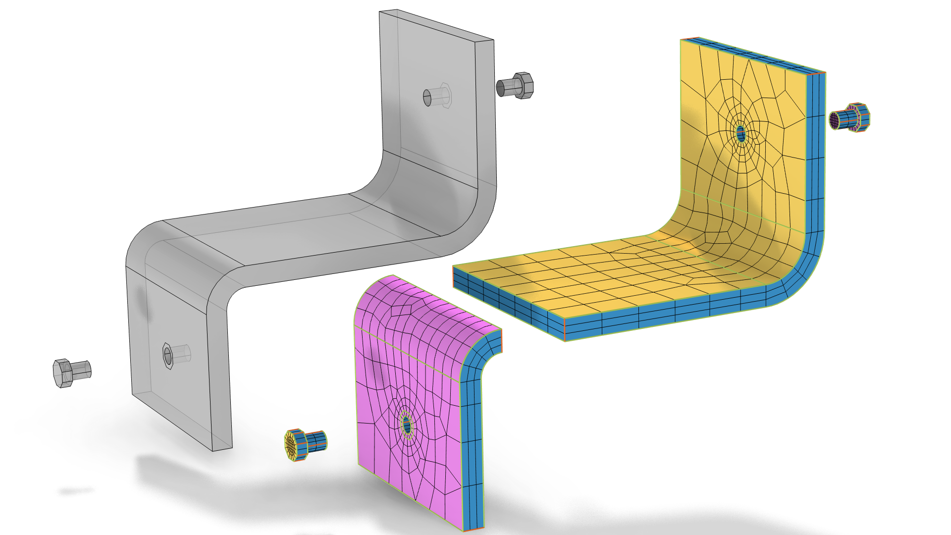 3D geometries of a gray, angled bracket and bolts are shown on the left, and the same geometry is shown on the right, with mesh elements applied and the faces colored in magenta, blue, and yellow.
To sweep a mesh through the angle bracket above (left), where there are imprints of the screws on opposite sides of the bracket, the domain can be partitioned in two (right) instead of imprinting the screw surfaces. Note that this geometry can be swept meshed with one Swept operation even though the two domains are swept in opposite directions.
3D geometries of a gray, angled bracket and bolts are shown on the left, and the same geometry is shown on the right, with mesh elements applied and the faces colored in magenta, blue, and yellow.
To sweep a mesh through the angle bracket above (left), where there are imprints of the screws on opposite sides of the bracket, the domain can be partitioned in two (right) instead of imprinting the screw surfaces. Note that this geometry can be swept meshed with one Swept operation even though the two domains are swept in opposite directions.
链接边的要求
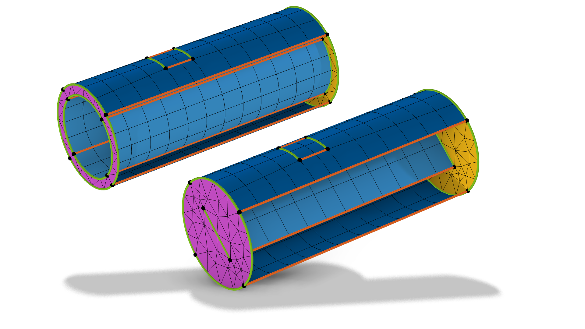
每个截面必须至少有两条链接边。对这一标准的另一种解释是,每个截面至少应有两个链接面。
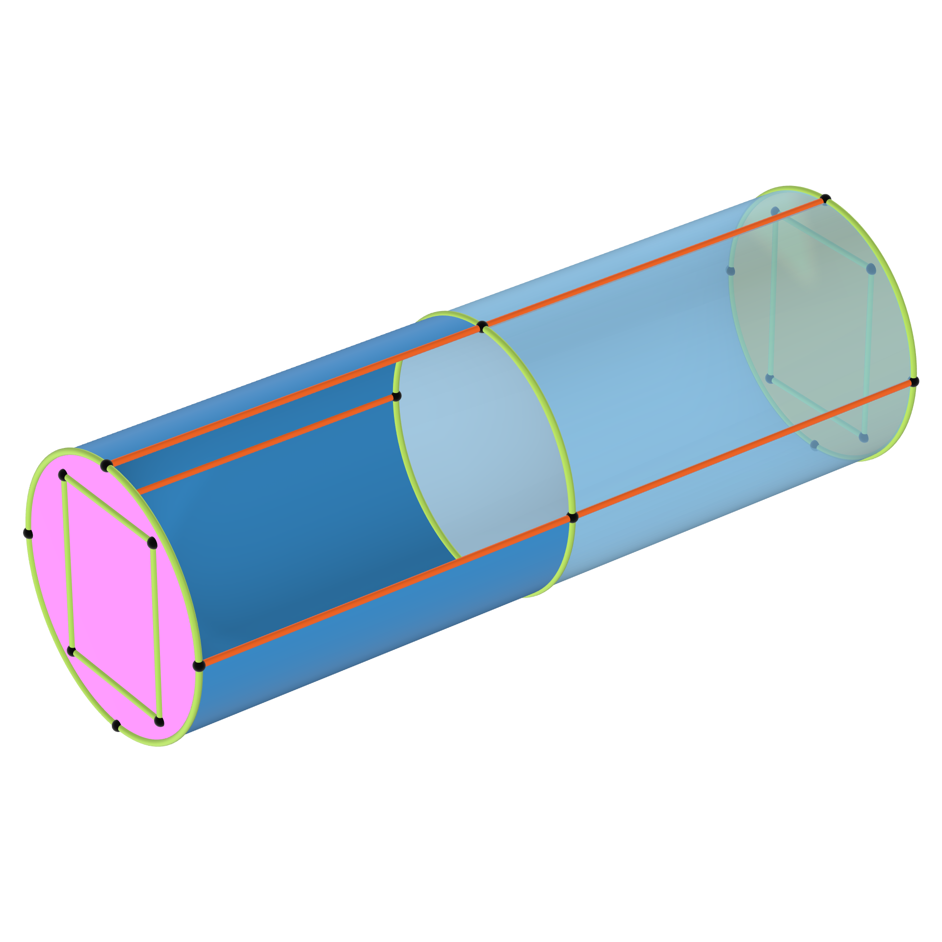 A domain with linking edges that can be swept meshed.
The domain can be swept meshed because there are at least two linking faces in both section (darker blue and lighter blue).
A domain with linking edges that can be swept meshed.
The domain can be swept meshed because there are at least two linking faces in both section (darker blue and lighter blue).
结束语
在这篇文章中,我们讨论了如何区分可以或不可以使用扫掠网格的域,以及四条简单的检查标准。如需了解文中几个模型示例的扫掠网格是如何生成的,请参阅附件中相应的 MPH 文件。在扫掠网格课程的第三部分,我们将介绍生成高质量网格需要考虑的最关键的因素。
请提交与此页面相关的反馈,或点击此处联系技术支持。