导入拓扑数据、网格和图像
COMSOL Multiphysics® 软件提供了将拓扑数据、网格和图像导入模型的功能。接下来,我们将为您介绍如何使用这些功能,并提供了一些可供您进一步学习如何实现这些功能的示例和参考资料。
导入网格
图像处理软件 Mimics 和 ScanIP 都可以导出由 3D 扫描生成的 COMSOL 格式的体网格,这些网格可以被直接导入网格序列中。另一种方法是导入 NASTRAN® 网格文件,这是一种许多软件程序都支持的格式,支持 2D 和 3D 网格,以及导入材料和基于材料的选择。这些导入通常在网格序列中完成。有关 COMSOL Multiphysics® 网格文件格式的详细信息,请参阅 COMSOL 用户手册中相关部分的内容: COMSOL Multiphysics Reference Manual > COMSOL Modeling Environment > The COMSOL Desktop > About the COMSOL Model File Formats 。如果您已经打开了软件,可以使用 帮助 窗口搜索并打开该文档。
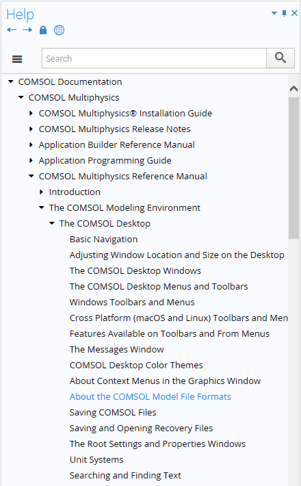 A screenshot of the Help window in COMSOL Multiphysics, with the COMSOL Desktop section expanded and the About the COMSOL Model File Formats section highlighted.
由于图像是直接转换成网格而不是几何对象,因此建议您按照如下讨论的方法,在将几何/网格导入 COMSOL Multiphysics®。之前先在第三方图像处理软件中对其进行微调。有关网格导入以及通过导入的网格创建模型几何的其他方面,我们在以下资源中进行了讨论:
其中还包括 NASTRAN®, STL, PLY 和 3MF 文件的导入。
导入拓扑数据
除了 参数化曲面 几何操作之外,还可以通过使用 插值、高程 和/或 图像 功能将拓扑数据、地理信息系统(GIS)数据、数字高程模型(DEM)数据 和 图像 导入 COMSOL® 软件。在 这篇博客 中,我们详细介绍了这一过程,即基于高程数据建立不规则形状的几何模型。
 A screenshot of the Definitions ribbon tab, with the More Functions button selected to show the different options for data import.
导入图像
您可以通过多种方式将图像导入 COMSOL Multiphysics®,来生成基于图像的几何模型。其中一种方法是使用 插值 功能。例如,这篇博客 讨论了基于图像信息的材料数据插值。
您还可以使用 图像到曲线 插件,在进行仿真分析时导入用于创建模型域的图像。 这篇博客 详细介绍了这一过程。
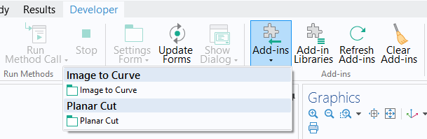 A screenshot of the Developer ribbon tab with the Add-ins button selected and the Image to Curve and Planar Cut add-ins shown in a drop-down menu.
点击 此处,阅读更多博客文章,了解关于不规则形状建模的场景,以及所使用的功能和策略。
请提交与此页面相关的反馈,或点击此处联系技术支持。