
使用偏微分方程(PDE)接口建模:矢量和张量方程组
本文为“使用偏微分方程(PDE)接口建模”系列课程的第 9 部分,将介绍更多关于建立偏微分方程组的知识。具体来说,我们将研究因变量代表矢量或张量场分量的情况,例如结构力学中的位移矢量和位移场分量。这些方程可以在 COMSOL Multiphysics® 软件中使用内置的平面应力接口或使用 系数形式偏微分方程 接口定义的用户自定义平面应力方程组进行设置。虽然使用预定义的平面应力接口要容易得多,但本文将重点介绍如何从头开始设置相应的方程组。这将帮助您为设置更通用的方程组做好准备,包括在 COMSOL Multiphysics® 中没有内置选项的方程组。
平面应力本构关系
有关平面应力和其他二维结构力学公式的介绍,请参阅博客 平面应力和平面应变的区别 。平面应力的本构方程有好几种不同的表述方法,我们将按照上述博客中介绍的方法,使用以下符号来表示平面应力的应力和应变之间的关系:


所有其他应力分量均等于零。
式中,应变张量分量分别为  ,
,  , and
, and  ;应力张量分量分别为
  ,
,  , and
, and  ;杨氏模量为
  ;泊松比为
;泊松比为  ;剪切模量为
  。
。
我们分别用 x 和 y 方向上的位移分量  和
和  来表示平面应力方程,有时将这些分量统称为位移矢量:

为此,我们需要了解位移分量与应变张量分量之间的关系:


其中
 称为 工程剪切应变。
请注意,为了让问题保持简单,我们将假定变形和旋转都很小。
纳维-斯托克斯方程
连续介质力学的无阻尼运动方程为

其中, 是质量密度;
 是外力密度,如重力;
 是应力张量。
根据静态平衡定律,我们可以得到平面应力的偏微分方程组。这个方程组可以看作是一个单一的矢量张量平衡方程,使用应力张量来表示:

代表(内部)应力张量 与外力密度 的平衡。
现在,我们将使用多变量系数形式偏微分方程组来重构这个方程:

其中,

式中, 不是标量,而是在强耦合方程组中与 “应力扩散系数” 相对应的弹性张量。
在使用 数学 接口设置平面应力方程组时,有几种接口可供选择:系数形式偏微分方程、一般形式偏微分方程 和 弱形式偏微分方程 接口。使用前两者非常复杂,在下面的推导中您将会看到。另一种不太复杂的方法是使用弱形式偏微分方程,您将在本课程的第 11 部分中看到。然而,理解弱形式需要更多的数学背景,因此我们将首先向您展示如何使用系数形式偏微分方程。请注意,使用 一般形式偏微分方程 与使用 系数形式偏微分方程 非常相似。
让我们用 系数形式偏微分方程 来建立平面应力方程。在三维空间中,平衡方程的组成部分可写成

对于二维平面应力,我们可以得到

利用方程组的这种形式,我们可以将平面应力本构关系写成应力和应变分量之间的张量关系:

COMSOL Reference Manual 文档的 Multiple Dependent Variables — Equation Systems 部分描述了如何使用系数形式偏微分方程来表示这种类型的本构关系。接下来,我们需要根据因变量 和 的梯度找到一种表述方法。
首先将应力张量排列成列向量,如下所示:

请注意, 在该列向量中出现两次,对应于应力张量  中的两个非对角项。
现在,我们根据位移梯度分量写出应力:

我们需要确定系数 中的各个条目。首先,可以这样写


但是,这还不够好,因为我们无法获得梯度分量的正确组合。
根据扩散系数分量可以进一步扩展为各向异性分量这一特性,继续研究:


接下来,我们可以把这种关系写成克罗内克(Kronecker)积的一种形式:


现在,将其与如下关系式进行比较
确定系数并回到原始的克罗内克积,我们可以看到

我们也可以把它写成

现在,我们就得到了纳维-斯托克斯方程:
在平面应力情况下,纳维-斯托克斯方程组对应于:

其中,

和

对应。
或者,我们也可以使用剪切模量的定义,将其写为

请注意,虽然在这种情况下材料是各向同性的,但强耦合偏微分方程问题的扩散系数却变成了(有点违反直觉的)各向异性。
边界条件
固体力学内置接口的平面应力选项提供了多个边界条件选项。让我们来看看其中的几个选项,以及如何使用系数形式偏微分方程实现它们。
我们将从如何实现边界载荷开始。对于这类边界条件,内置接口提供了 单位面积的力、单位长度的力、总力 和 压力 选项。
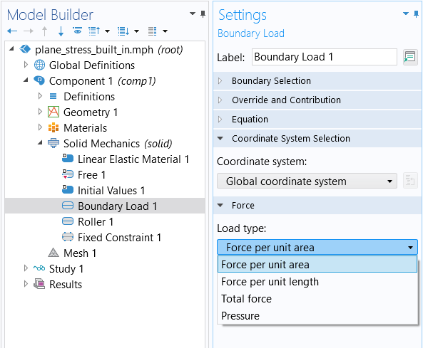
边界载荷 边界条件的 载荷类型 设置选项。
指定 单位长度的力 选项要求我们指定两个矢量分量:

将其与系数形式偏微分方程的 通量/源 边界条件进行比较:

我们可以将其输入为

指定 压力 的选项要求我们给出一个标量压力  :
:

其中,右侧的负号是由于法向量被定义为从固体边界向外的方向。请注意,负压通常被称为 张力。
我们可以将其输入为

再来看约束条件,使用内置接口,我们可以在两个位移变量中设置 固定约束 边界条件:

或列分量:

我们还可以设置一个 辊支承 约束,限制移动仅在边界的法线方向上发生。这可以用公式写成

这是一个标量方程。我们可以选择对方程组的第一“行”施加这一约束,而不对第二“行”施加约束。
为了完全约束边界,我们可以添加第二个约束条件

其中, 是切向量。请注意,在三维空间中,为了对边界进行完全约束,我们需要使用两个切向量来实现两个切向约束。然后,通过选择性地使用切向和法向约束的不同组合,可以得到各种类型的约束。不过,要完全约束边界,当然可以更方便地使用前面描述的 固定 约束条件。
带圆孔的矩形板,使用内置的实体力学接口
现在,让我们来看看上述 博客 中的例子。这个例子很简单,考虑一块中心有一个圆孔的矩形钢板。矩形宽 2 米,高 1 米,孔位于矩形中心,半径为 0.2 米。
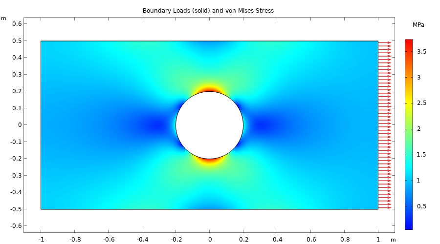
带孔的矩形板的边界载荷和 von Mises 应力。
如下图所示,在本例中我们使用了极精细的网格设置来离散模型的几何结构。
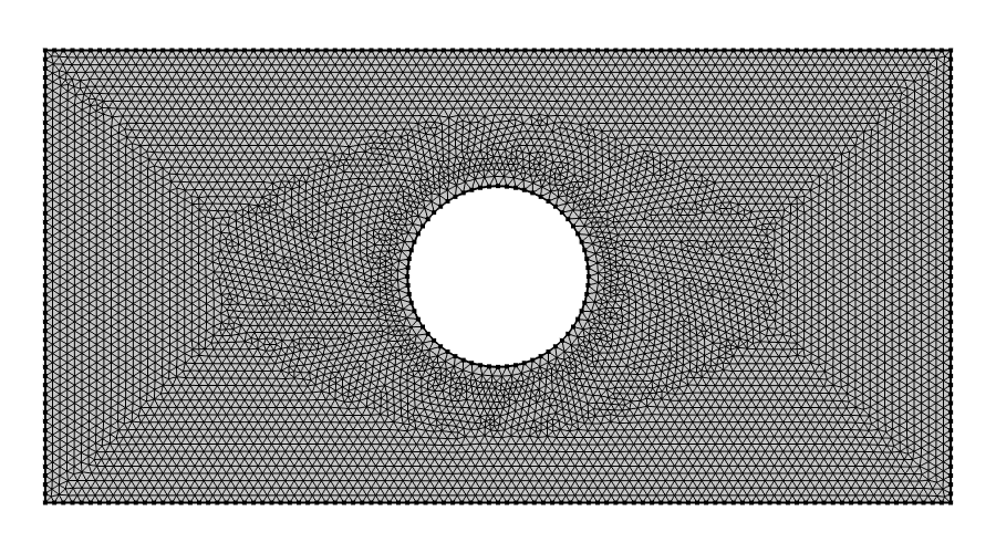
矩形板示例中使用的网格。使用的单元类型是二阶三角形拉格朗日单元。
在本示例模型中,右边界施加了 1 MPa (1e6 N/m2) 的拉伸载荷,左边界施加了辊支承约束。为避免不必要的垂直运动,左下角的点受到完全约束。下图显示了接口中各部分的设置。
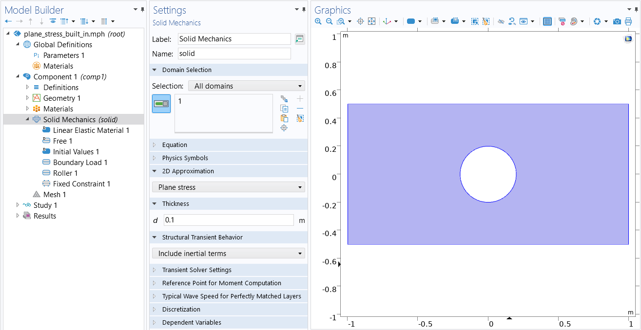 The COMSOL Multiphysics UI showing the Model Builder with the Solid Mechanics interface selected, the corresponding Settings window, and the rectangular plate in the Graphics window.
固体力学接口,二维近似 设置为 平面应力。所用材料为 结构钢,可从 内置 材料库分支中获取。
The COMSOL Multiphysics UI showing the Model Builder with the Solid Mechanics interface selected, the corresponding Settings window, and the rectangular plate in the Graphics window.
固体力学接口,二维近似 设置为 平面应力。所用材料为 结构钢,可从 内置 材料库分支中获取。
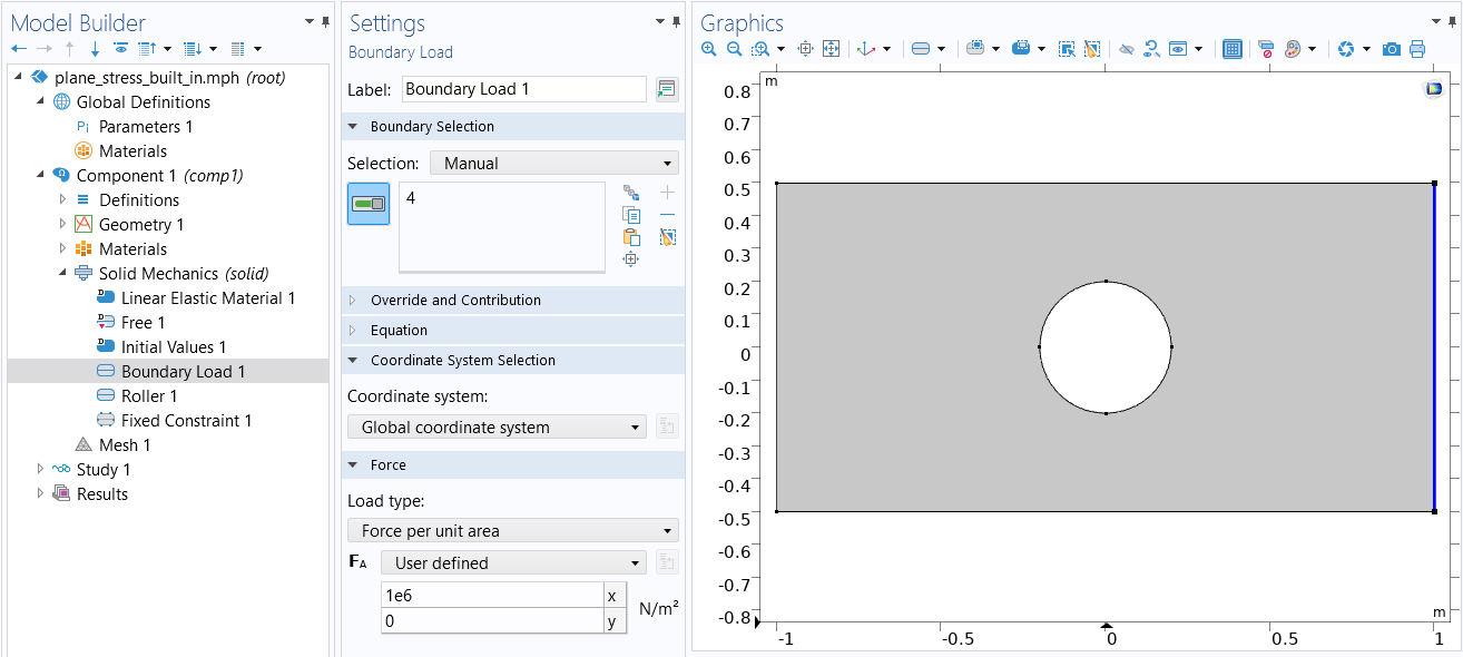 The COMSOL Multiphysics UI showing the Model Builder with the Boundary Load boundary condition selected, the corresponding Settings window with Force per unit area selected as the Load type, and the Graphics window showing the rectangular plate.
拉伸载荷的边界条件设置。
The COMSOL Multiphysics UI showing the Model Builder with the Boundary Load boundary condition selected, the corresponding Settings window with Force per unit area selected as the Load type, and the Graphics window showing the rectangular plate.
拉伸载荷的边界条件设置。
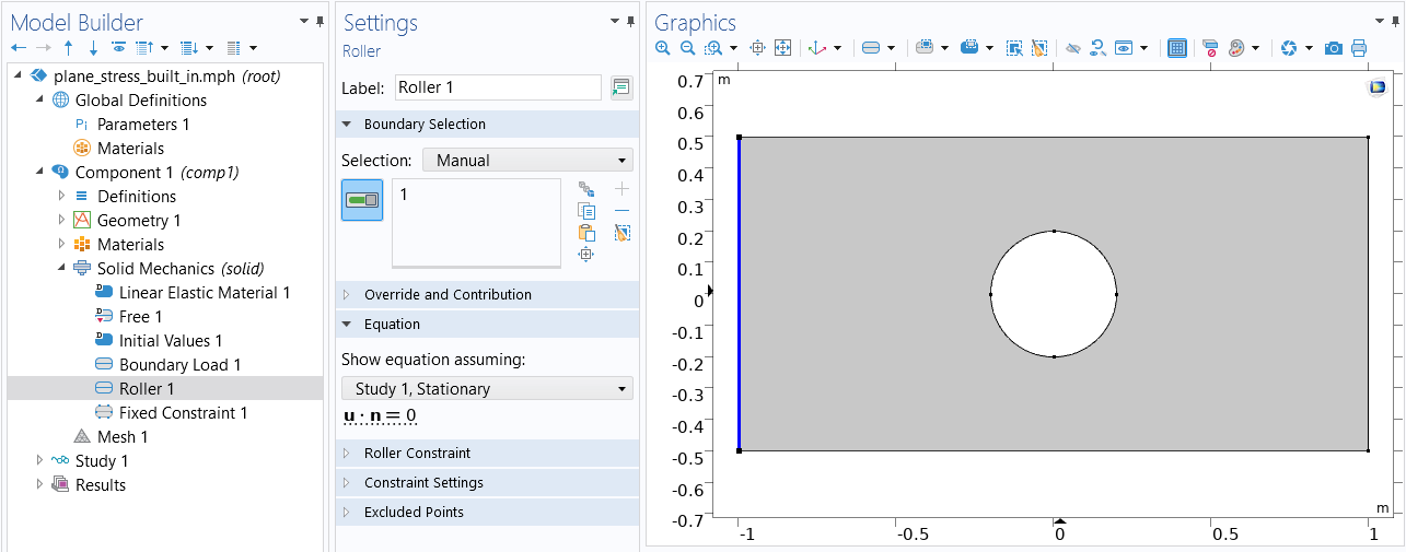 The COMSOL Multiphysics UI showing the Model Builder with the Roller constraint selected, the corresponding settings, and the Graphics window showing the rectangular plate.
辊支承 约束边界条件。
The COMSOL Multiphysics UI showing the Model Builder with the Roller constraint selected, the corresponding settings, and the Graphics window showing the rectangular plate.
辊支承 约束边界条件。
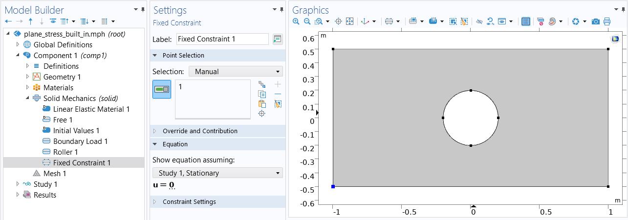 The COMSOL Multiphysics UI showing the Model Builder with the Fixed Constraint boundary condition selected, the Fixed Constraint settings, and the Graphics window showing the rectangular plate.
左下角的点被完全约束。
下面的图表显示了求解后可以评估的一些结果量。
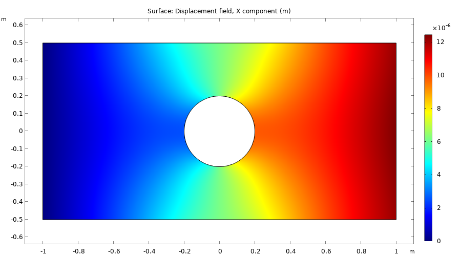
x 位移场,u。
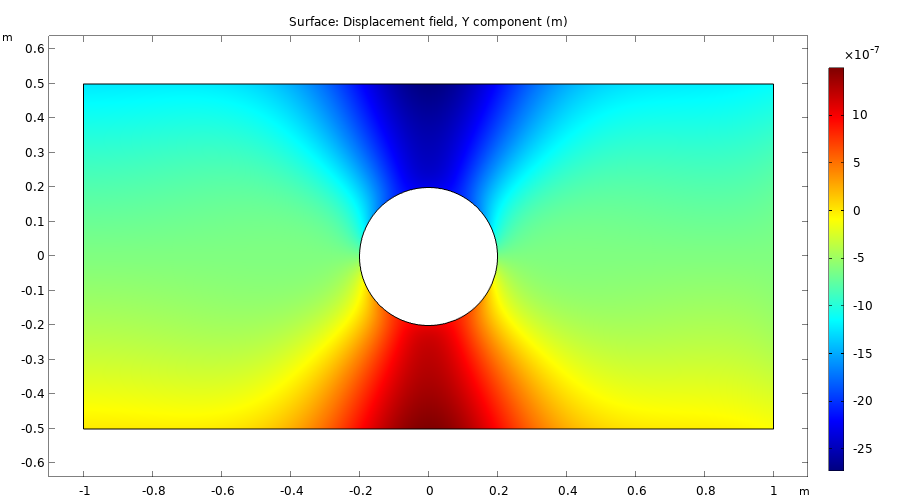
y 位移场,v。
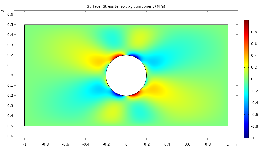
剪切应力 sxy。
带圆孔的矩形板,使用系数形式偏微分方程接口
现在,我们将使用基于方程建模的方法重新建立这一模型。
为了设置平面应力方程,下图显示了系数形式偏微分方程,其中有两个因变量 u 和 v,分别表示 x 和 y 方向的位移。默认 离散化 设置为 二次拉格朗日 形函数,有时也称为 二阶等参三角有限元。
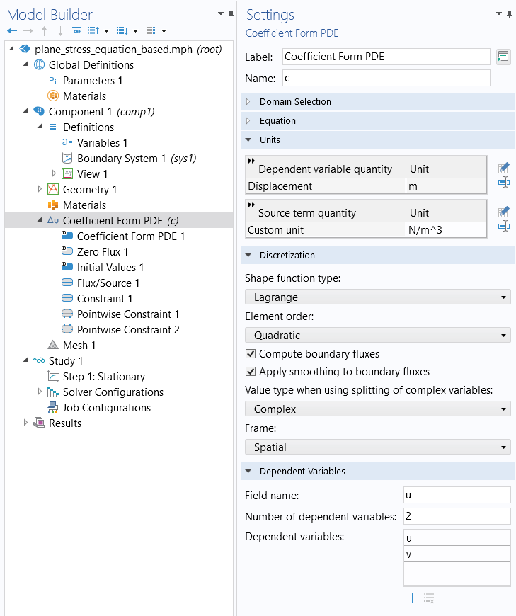
系数形式偏微分方程 的设置。
在 系数形式偏微分方程 接口的 设置 窗口中,将 因变量 的单位改为 位移(米),将 源项量 的单位改为 N/m^3(该单位没有内置选项)。
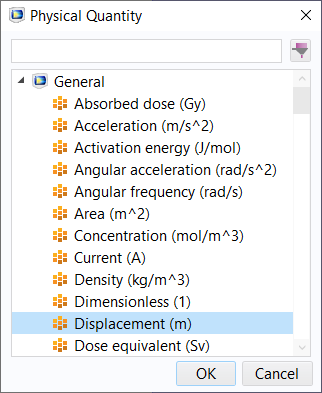
位移(m)的单位选项。
请注意,您也可以在模型向导中设置因变量和单位,如下图所示。
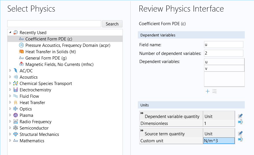
模型向导 中的 选择物理场 窗口,用于更改因变量的名称、数量和单位。
我们需要为材料属性和厚度定义一些参数。
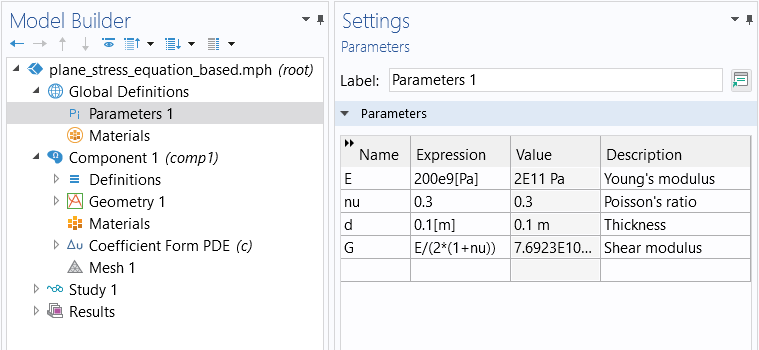
平面应力示例的材料参数
在求解之前或求解过程中不需要厚度,但需要在对结果进行后处理时获得正确的单位。
回想一下,纳维斯托克斯方程的扩散系数可以写成
下图显示了如何使用 全角 和 对角线 选项输入扩散系数分量。
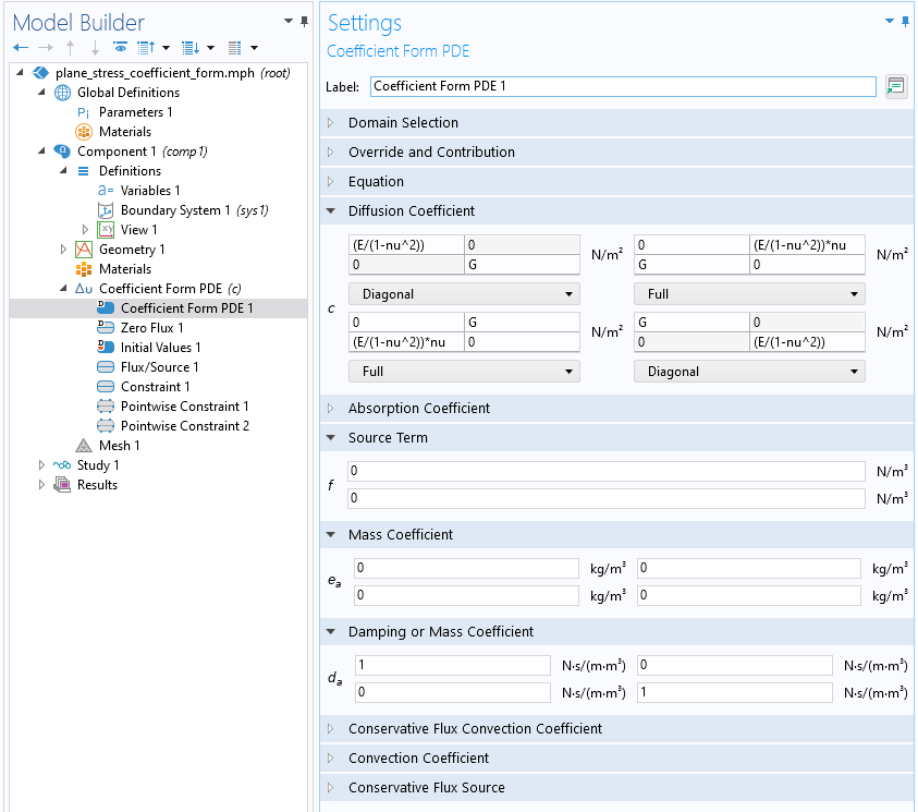 The Model Builder with the Coefficient Form PDE interface selected and the corresponding Settings window with the Diffusion Coefficient, Source Term, Mass Coefficient, and Damping or Mass Coefficient sections expanded.
平面应力的 扩散系数 设置。
The Model Builder with the Coefficient Form PDE interface selected and the corresponding Settings window with the Diffusion Coefficient, Source Term, Mass Coefficient, and Damping or Mass Coefficient sections expanded.
平面应力的 扩散系数 设置。
如果有一个体载荷 ,其中有两个分量

在 源项 栏中输入这些信息。
由于我们使用的是 稳态 研究,因此本模型中忽略了动力学系数 质量系数 和 阻尼系数。
为了将边界载荷指定为 1 MPa = 1e6 N/m3 的拉伸载荷,使用 通量/源 边界条件,并设置  = 1e6 和
  = 0,如下图所示
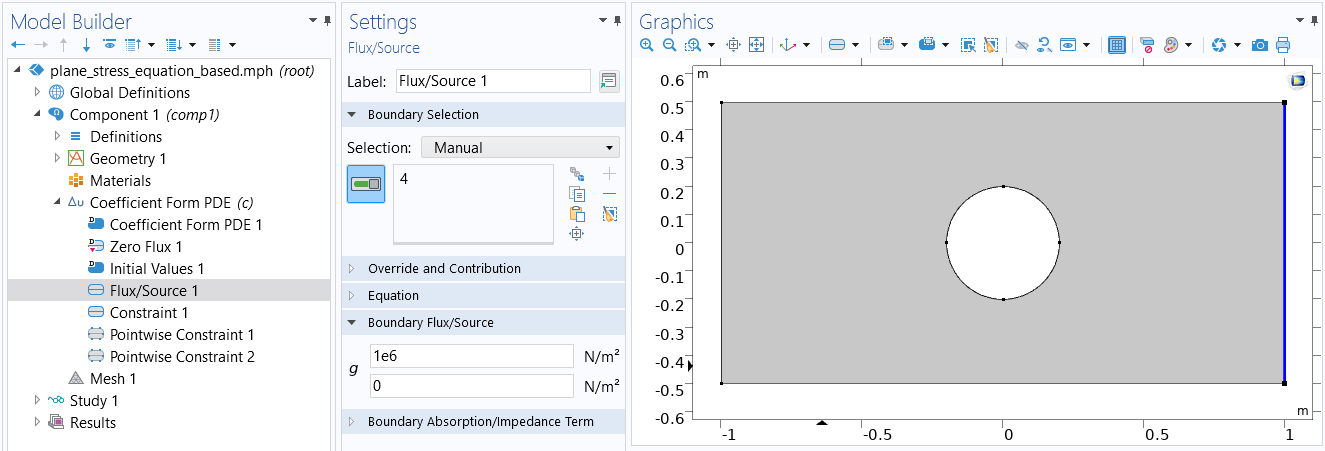
拉伸载荷的设置。
一般情况下,边界既不是水平也不是垂直的,可以使用变量 nx 和 ny 来定义边界条件,它们代表边界上从实体域向外的单位法向量分量。例如,在这种特殊情况下,我们可以通过输入 = 1e6*nx 和 = 1e6*ny 来获得相同的边界条件。
为了指定辊支承约束,使用如下约束边界条件
或按分量写出
nx*u+ny*v
我们可以在一般约束编辑框中做如下指定

需要注意的是,由于有两个方程,u 和 v 变量各一个,因此我们会进入两个约束编辑框。然而,辊支承约束是一种标量约束,因此我们只需使用其中一个编辑框,如下图所示。
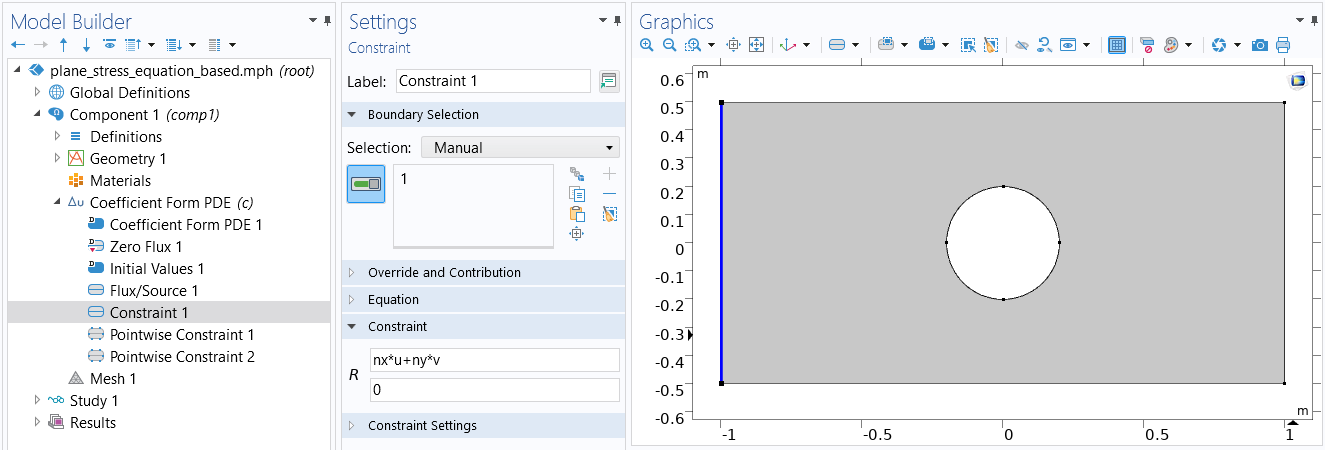 The COMSOL Multiphysics UI showing the Model Builder with the Constraint boundary condition selected, the corresponding settings, and the Graphics window showing the rectangular plate.
辊支承约束的设置。
The COMSOL Multiphysics UI showing the Model Builder with the Constraint boundary condition selected, the corresponding settings, and the Graphics window showing the rectangular plate.
辊支承约束的设置。
下一步是固定矩形左下角点的位移。内置接口提供了一个包含两个约束条件的特征节点。但是,在基于方程的接口中,我们需要使用两个 逐点约束 特征,一个用于 u,另一个用于 v,如下图所示。
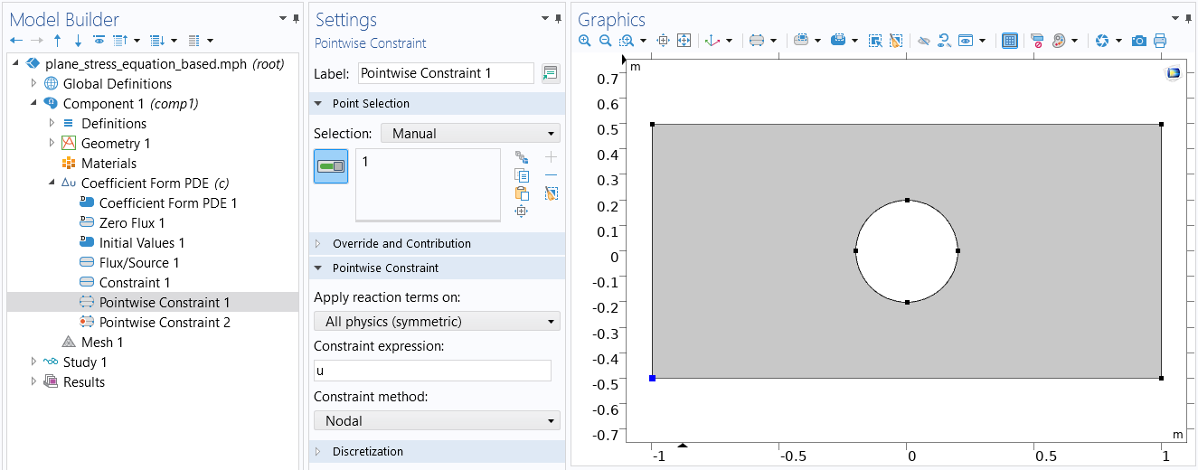 The COMSOL Multiphysics UI showing the Model Builder with the Point Constraint boundary condition selected, the corresponding Settings window, and the Graphics window showing the rectangular plate.
位移变量 u 的 逐点约束 设置。
The COMSOL Multiphysics UI showing the Model Builder with the Point Constraint boundary condition selected, the corresponding Settings window, and the Graphics window showing the rectangular plate.
位移变量 u 的 逐点约束 设置。
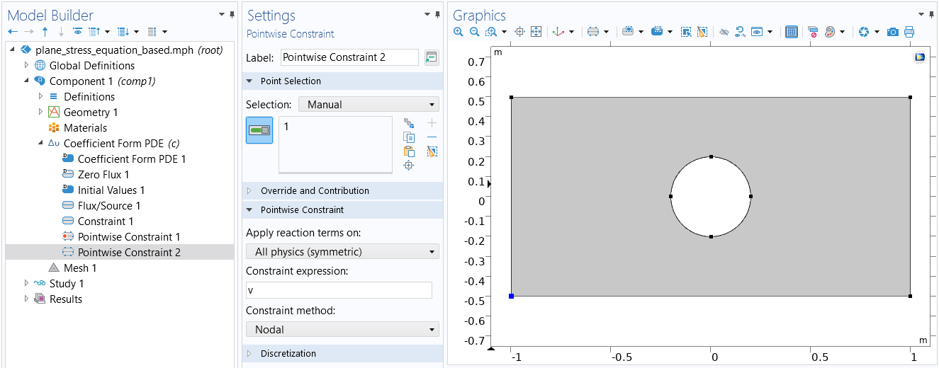 The COMSOL Multiphysics UI showing the Model Builder with a second Point Constraint boundary condition selected, the corresponding settings, and the Graphics window showing the rectangular plate.
位移变量 v 的 逐点约束。
The COMSOL Multiphysics UI showing the Model Builder with a second Point Constraint boundary condition selected, the corresponding settings, and the Graphics window showing the rectangular plate.
位移变量 v 的 逐点约束。
为方便起见,我们现在可以定义一组希望可视化或评估的变量。下图显示了应变和应力张量分量以及 von Mises 应力的变量设置。
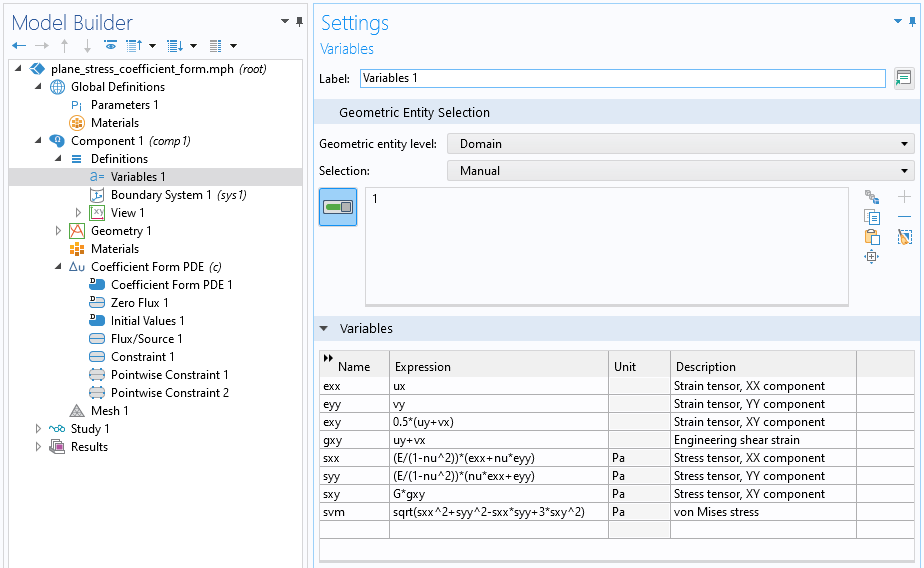
常用结构分析量的设置。
现在,我们来绘制这些量,可以看到它们与内置物理场接口的结果完全一致,正如我们正确输入了所有方程所期望的那样。下图显示了基于方程的平面应力解中的一个应力张量分量。
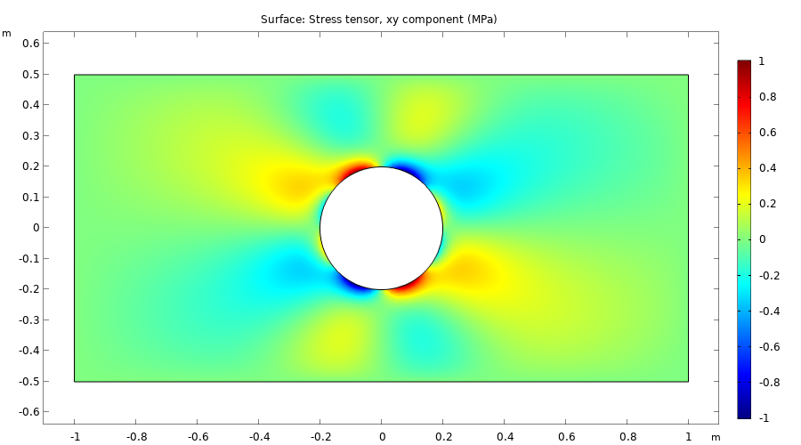
应力张量分量 sxy。
使用系数形式 PDE 建立平面应力方程需要很多步骤。在接下来的几部分中,我们将学习弱形式,它提供了一种更紧凑但也更抽象的方法来模拟相同的方程。
进阶学习
虽然您可以下载本文随附的示例模型,但我们建议您先按照本文介绍的建模方法完全从头开始自己建立模型。之后,您可以打开示例模型文件,将使用 系数形式偏微分方程 接口建立的模型和使用软件预定义物理场接口建立的模型进行比较和探索,这将加强您从头开始学习建立方程组的能力。
请提交与此页面相关的反馈,或点击此处联系技术支持。


