
构建高质量的扫掠网格
在上一篇文章中,我们讨论了在 COMSOL Multiphysics® 中使用 扫掠 操作进行网格划分时对几何结构的要求。接下来,我们将进一步讨论如何获得高质量的扫掠网格。那么,要生成高质量的扫掠网格,最重要的设置和考虑因素是什么呢?本文我们将讨论这个问题以及更多其他问题。请注意,我们假设将要进行扫掠网格操作的每一个域都满足上一篇文章中讨论的所有要求。
选择源面和目标面
在本课程的第二部分,我们了解到扫掠的方向非常重要,因为软件需要将源面映射到目标面上。这是否意味着我们需要手动选择源面和目标面呢?不一定。大多数情况下,软件会自动检测源面和目标面,只有在扫掠方向不明确的情况下,才需要手动选择源面或目标面:扫掠可能有多种不同的路径,但是其中一种是最合适的路径,这将取决于物理场。在并行地对多个域进行网格划分时,更是如此。不过,即使在这种情况下,通常只需要选择源面就足够了,因为 COMSOL Multiphysics® 会根据您选择的源面自动检测目标面。
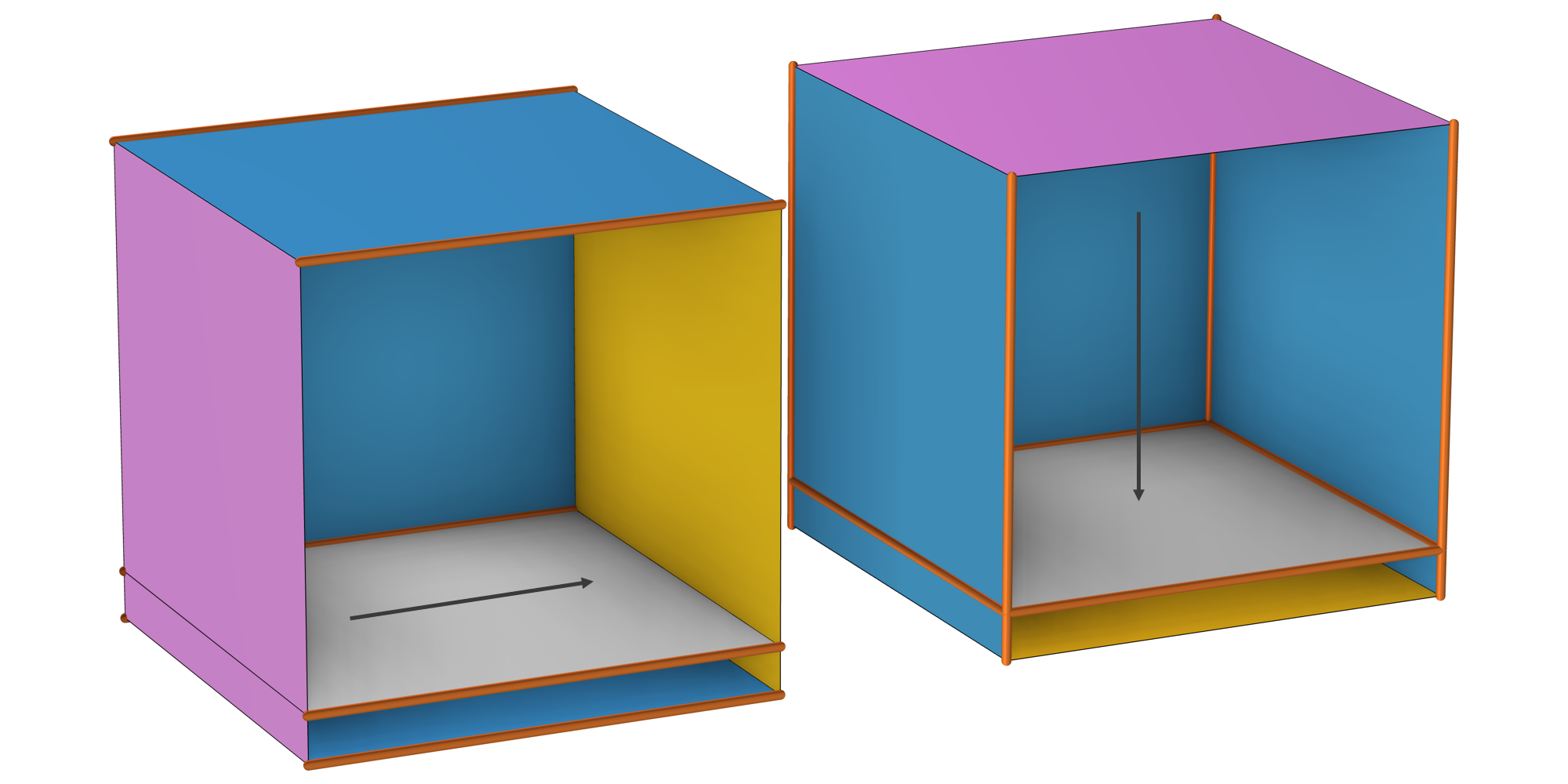
使用 扫掠 对长方体进行网格划分时,会存在两个不同的扫掠方向(如箭头所示)。左侧视图中, COMSOL Multiphysics® 自动选择了源面(洋红色)和目标面(橙色)。右侧视图中,使用了用户定义的源面进行扫描,其中 COMSOL Multiphysics®已经自动检测了目标面。(为便于查看,隐藏了前侧面。)
面网格由扫掠操作自动生成:源面用四边形(即 quad)网格(也可选择三角形)划分,链接面用 映射 网格划分,目标面网格与源面一致(如果您想了解更多其他方法,详见 文档)。下图示例中,源面使用了三角形网格进行划分。
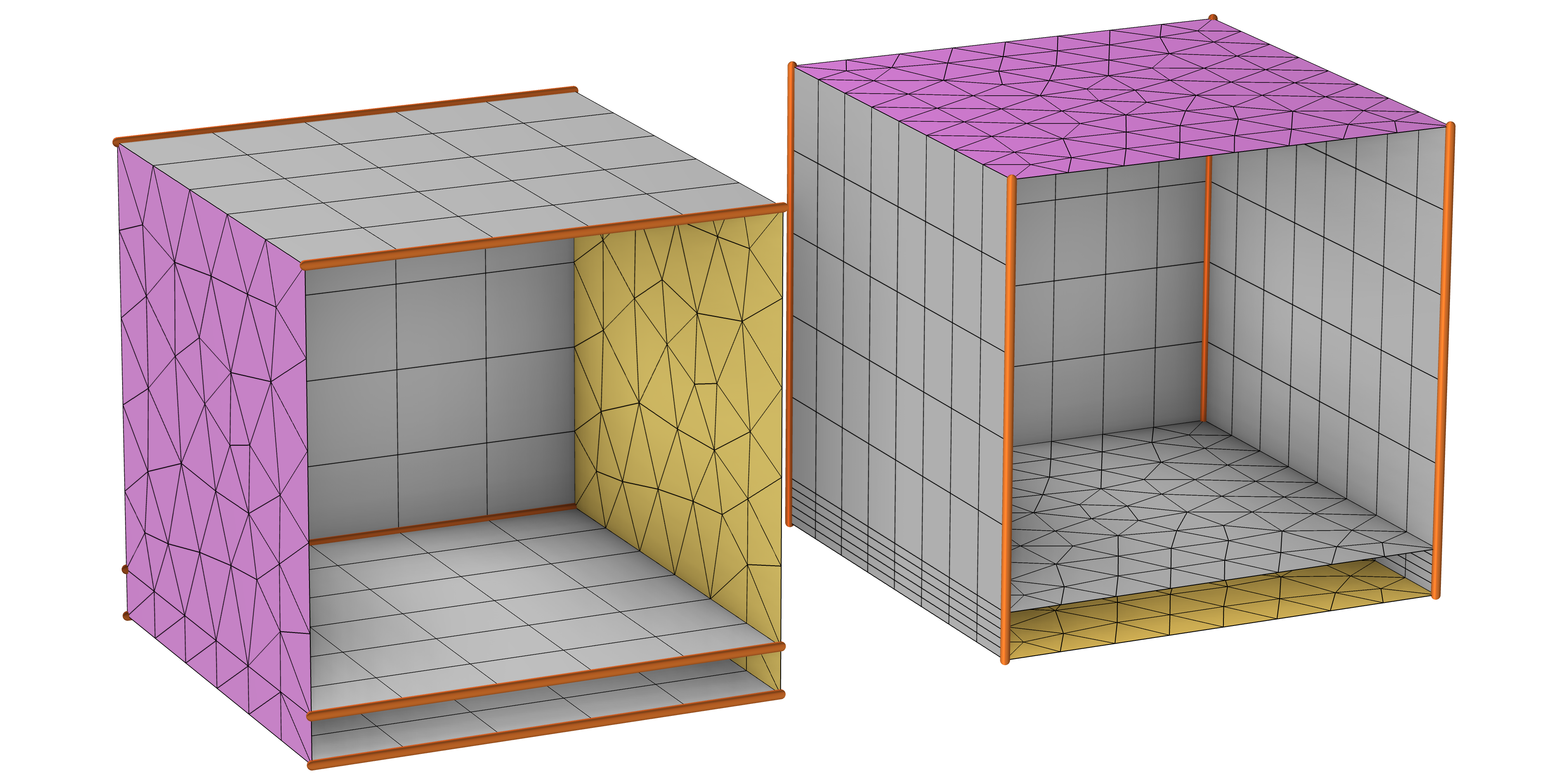
采用两种扫掠方式生成的面网格(隐藏了前侧面,用灰色网格表示链接面网格)。右侧扫掠网格的源面是由用户定义的,左侧网格的源面是由软件自动识别的(在这两种情况下, 分布 字节点都是沿着扫描方向作用的,下文将详细介绍),因此生成了两种不同的网格。根据物理场的不同,一种网格可能优于另一种网格。
也可以选择先手动生成源面的面网格,然后再添加 扫掠 网格操作。Read more about this in the section When and How to Premesh the Source Faces。
控制网格大小和分布
我们已经在博客文章 使用不同尺寸设置进行网格划分的最佳方式 进行了详细解释,一个好的划分策略是使用一个具有多个局部大小属性的网格划分操作,而不是重复多个网格划分操作。这也与网格划分算法的 并行化 有关。 扫掠操作也不例外,让我们来看看有哪些属性可用。如果想添加属性,请右键单击 扫掠 节点病选择 大小 或 分布。
大小
大小 节点常用于设置域中的最大或最小单元尺寸,其数值可能取决于物理变量、参数或包含变量和参数的表达式。For more control over the size of the mesh elements on the specific source faces, see the section "When and How to Premesh the Source Faces" below.
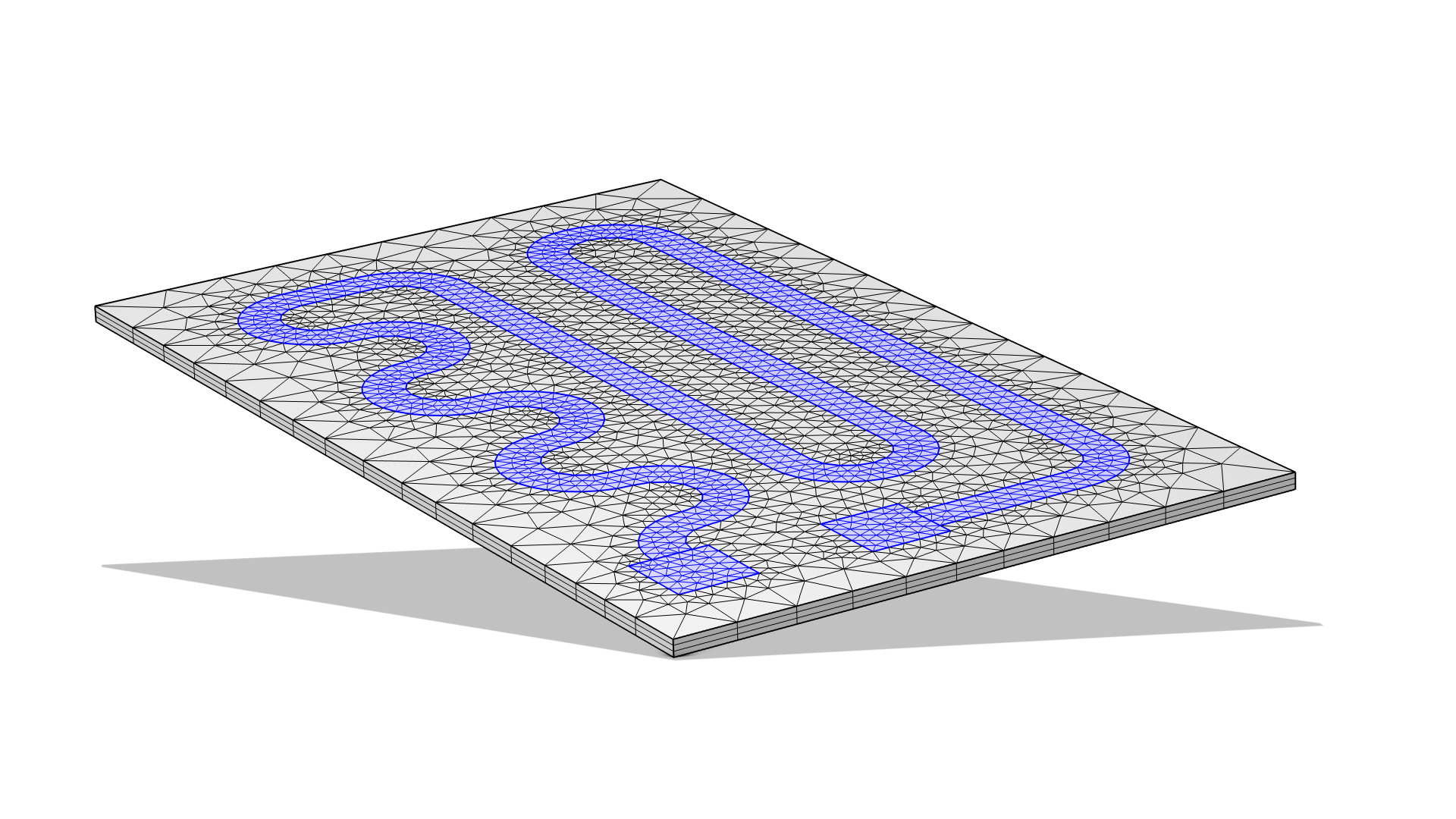 The boundaries of a heating element are selected in blue.
Adding a Size attribute to control the element size on the selected (blue) boundaries of this heating circuit.
The boundaries of a heating element are selected in blue.
Adding a Size attribute to control the element size on the selected (blue) boundaries of this heating circuit.
分布
For the Swept operation, the Distribution attribute specifies how many mesh element layers there are along the sweep direction. This functionality is commonly used for infinite element domains, as is shown for the motor and mobile device model examples below. The layers of mesh elements in that domain allow the wave energy to be gradually absorbed without spurious reflections, emulating the device in an infinite domain and keeping the focus within the immediate vicinity. If you want to control the distribution along an edge, you need to premesh it, as explained below. The result is determined by the Distribution Type and the associated settings. If a similar element size is wanted in several domains, consider using a Size attribute instead.
See the article "Geometry and Mesh Setup for Modeling Regions of infinite Extent" for more information on handling infinite element domains.
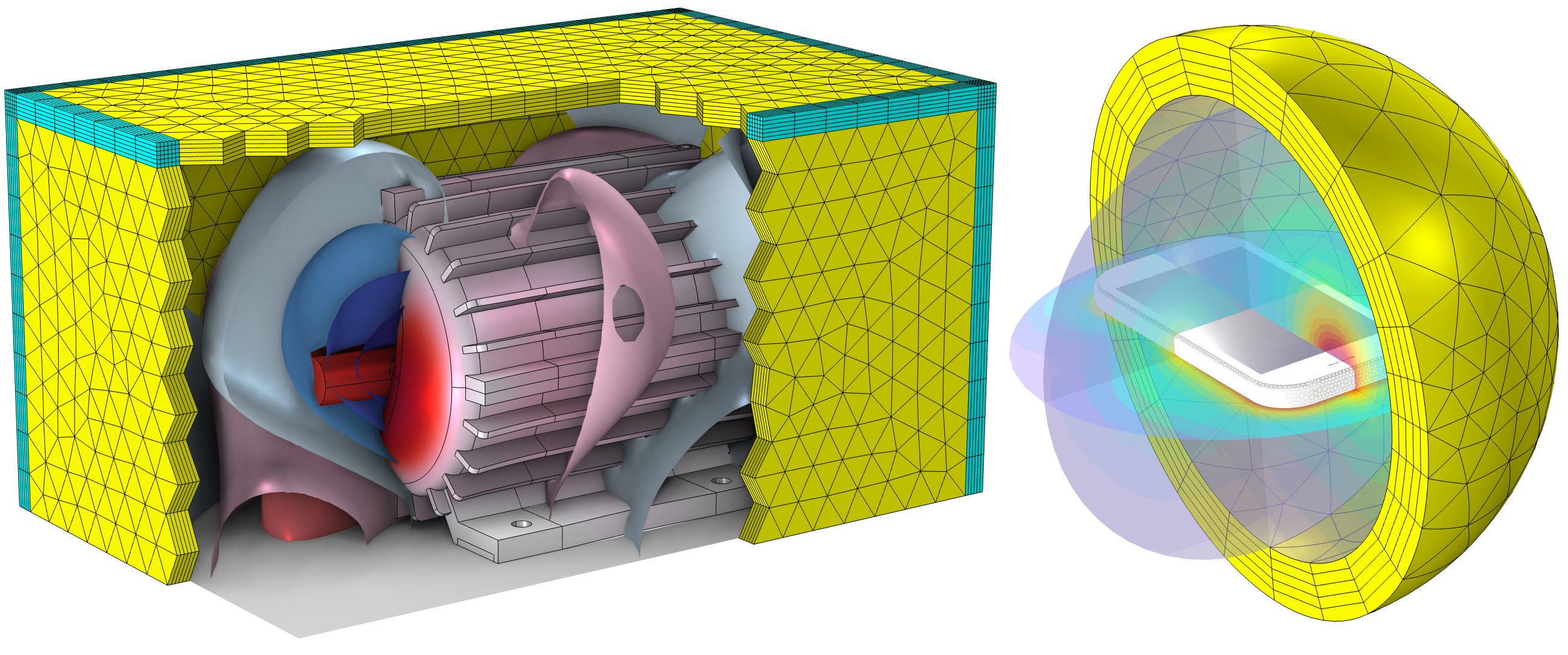 On the left, a yellow rectangular box with triangular shapes on the surface and cyan rectangular shapes along the edges an corners, and on the right, concentric yellow spherical layers made up of rectangular elements surround a rectangular device.
The boundaries around an electric motor (left) and a mobile device (right) are meshed with layers using the Swept and Distribution nodes to emulate the objects in an infinite domain.
On the left, a yellow rectangular box with triangular shapes on the surface and cyan rectangular shapes along the edges an corners, and on the right, concentric yellow spherical layers made up of rectangular elements surround a rectangular device.
The boundaries around an electric motor (left) and a mobile device (right) are meshed with layers using the Swept and Distribution nodes to emulate the objects in an infinite domain.
默认的 分布类型 为固定单元数。_ 将此设置更改为 预定义 可指定线性或指数增长的单元分布,有助于相邻域的单元之间平滑的过渡,适用于某些物理场(如流体力学)。
在设置任何预定义分布时,单元数  和单元大小比
  (最大单元大小
  和最小单元大小
  之间的比)都是输入的数值:
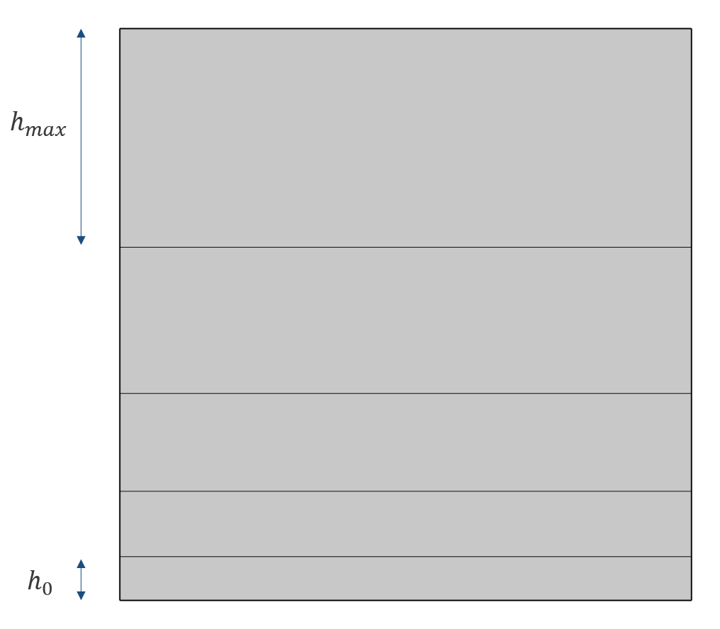 A graph shows the lengths of the domains in an asymmetric distribution.
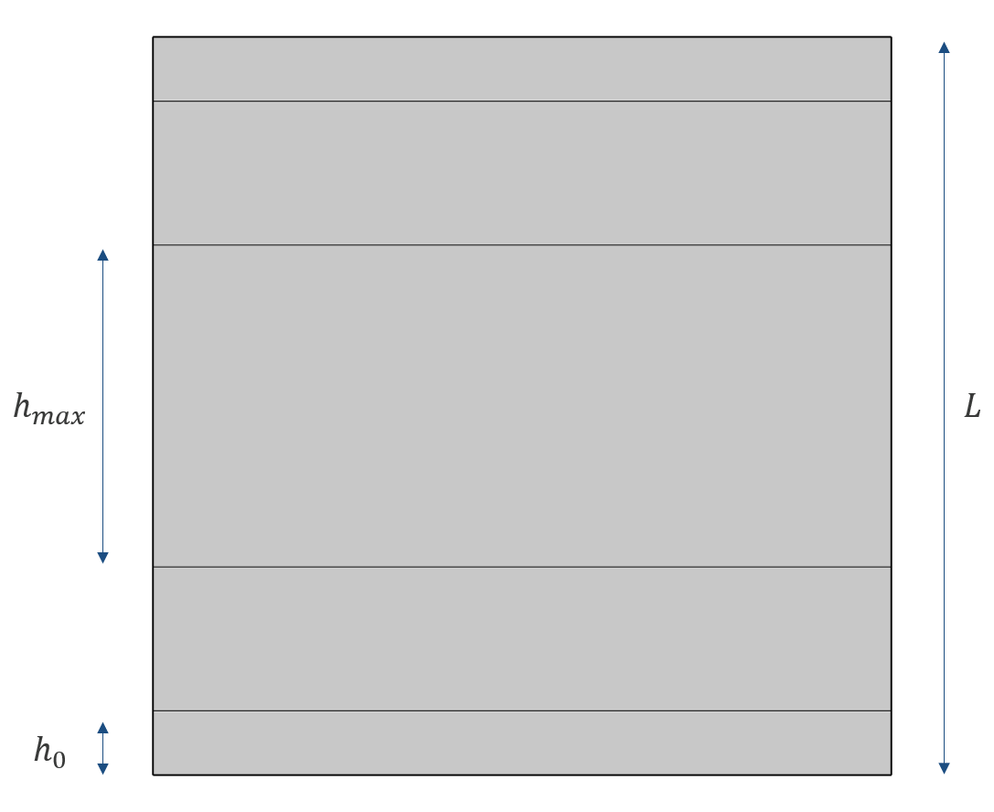 A graph shows the lengths of the domains in a symmetric distribution.
 。
。
虽然在大多数情况下,可以通过手动调整参数来获得满意的网格,但您可能希望对网格的增长速度有更多的控制。下表列出了非对称分布的一些关系式。对称分布取决于 的奇偶性,但如果将 和 分布替换为  和
和  ,则对称分布近似(当 为偶数时相等)。
| 表达式 | 线性 | 指数 |
|---|---|---|
 |
 |
 |
 |
 |
 |
 |
 |
 |
其中, 和相邻单元( )之间的最大局部增长率
  有可能是已知的。
比如说,您希望 与横截面上的网格大小相等,而最大增长率由全局的大小节点确定。如何推导出 和 呢?让我们用指数分布来找出答案。
一般来说,最大单元的大小是有上限的,因此
 。第一步是确保即使在
  时也是如此(我们的目标是使用尽量少的单元数划分网格)。因此,从上表的最后一行可以得到:
由此,通过重新排列上表最后一行和
的定义,可以推导出 和  :
:
最后,利用上表第二行,
可以近似为与  最接近的整数。
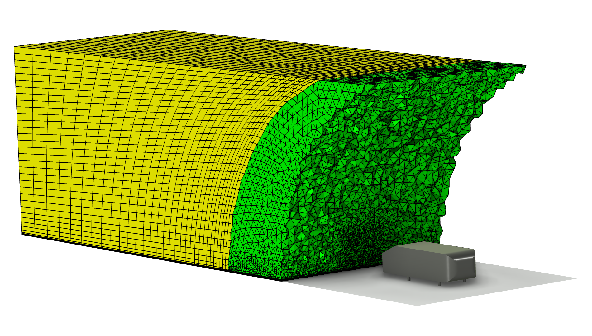 The mesh for the fluid flow domain surrounding an Ahmed body, where the coarser mesh that's farther from the body is yellow and the finer mesh that's closer to the body is green.
为了平滑地增加网格单元的大小,利用指数分布定义了 Ahmed 类车体 后方的 扫掠 网格(黄色)。
The mesh for the fluid flow domain surrounding an Ahmed body, where the coarser mesh that's farther from the body is yellow and the finer mesh that's closer to the body is green.
为了平滑地增加网格单元的大小,利用指数分布定义了 Ahmed 类车体 后方的 扫掠 网格(黄色)。
添加边界层网格有时可以替代在扫掠中使用预定义分布。如下图所示。
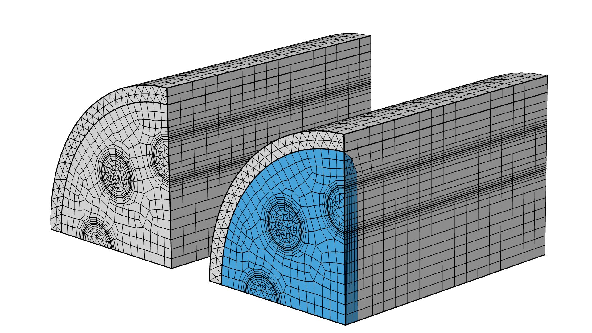
蒸汽重整器 教程模型的几何结构。这个示例在圆柱体的入口处使用了边界层网格,而不是对称分布。蓝色表示边界层网格单元。
There is also the option to manually generate the surface mesh for the source face first, and then follow this with adding a Swept mesh operation. Doing so enables you to use mesh operations (e.g. Size and Distribution subnodes) to achieve a desired face meshing on the source face, which you can then sweep into a 3D mesh. Examples of which can be seen here.
在什么情况下需要对源面预划分网格?如何操作?
虽然可以通过 扫掠 操作自动完成域的面网格划分,但在某些情况下,您需要对执行 扫掠 操作的源面进行网格预划分,即通过预先的操作划分网格。
需要注意的是,在添加 扫掠 操作之前已经被划分网格的所有面都可能会被自动选择为源面。必要情况下,您可以使用 自由四边形,自由三角形,或 映射 操作对源面进行网格预划分(examples of which can be seen here)。在对源面进行网格预划分的一些场景中,可以使用:
- 大小 属性,用于控制源面网格大小。
- 边界层网格。对于扫掠网格,建议扫掠之前在源面添加边界层(见下图)。
- 源面上的映射网格。
 Three side-by-side figures of the Steam Reformer tutorial model geometry showing the boundary layer mesh.
蒸汽重整器 教程模型的几何结构。首先在源面添加了边界层网格。
Three side-by-side figures of the Steam Reformer tutorial model geometry showing the boundary layer mesh.
蒸汽重整器 教程模型的几何结构。首先在源面添加了边界层网格。
注意:如果在进行扫掠 操作前,已对多个面进行了网格划分,请确保: 1. 使用 映射 操作对链接面进行网格划分。 2. 目标网格与源网格精确匹配。
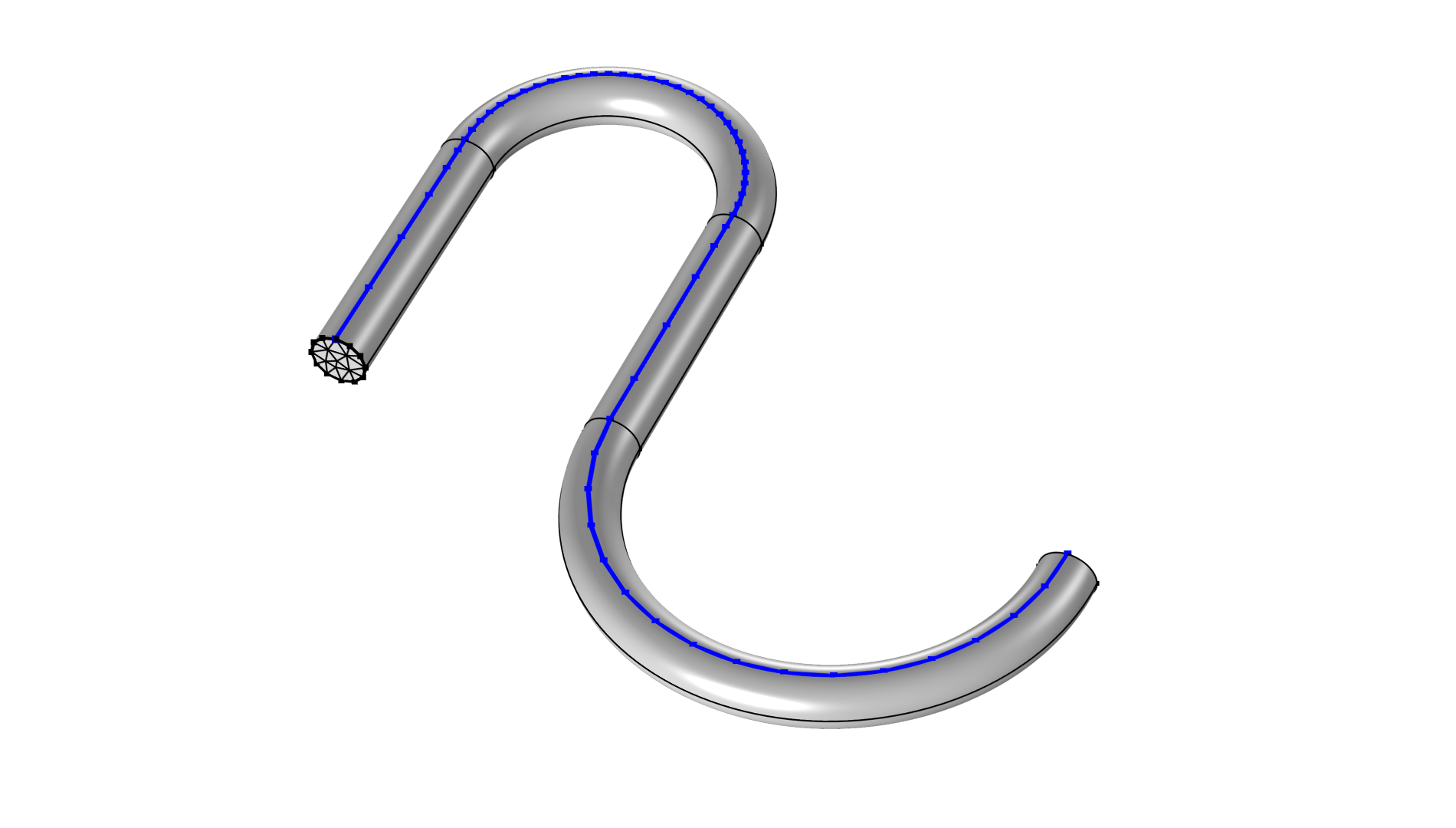
Premeshing edges can also be useful. For example, the Edge operation can take the curvature factor into account while maintaining a continuous growth rate change.
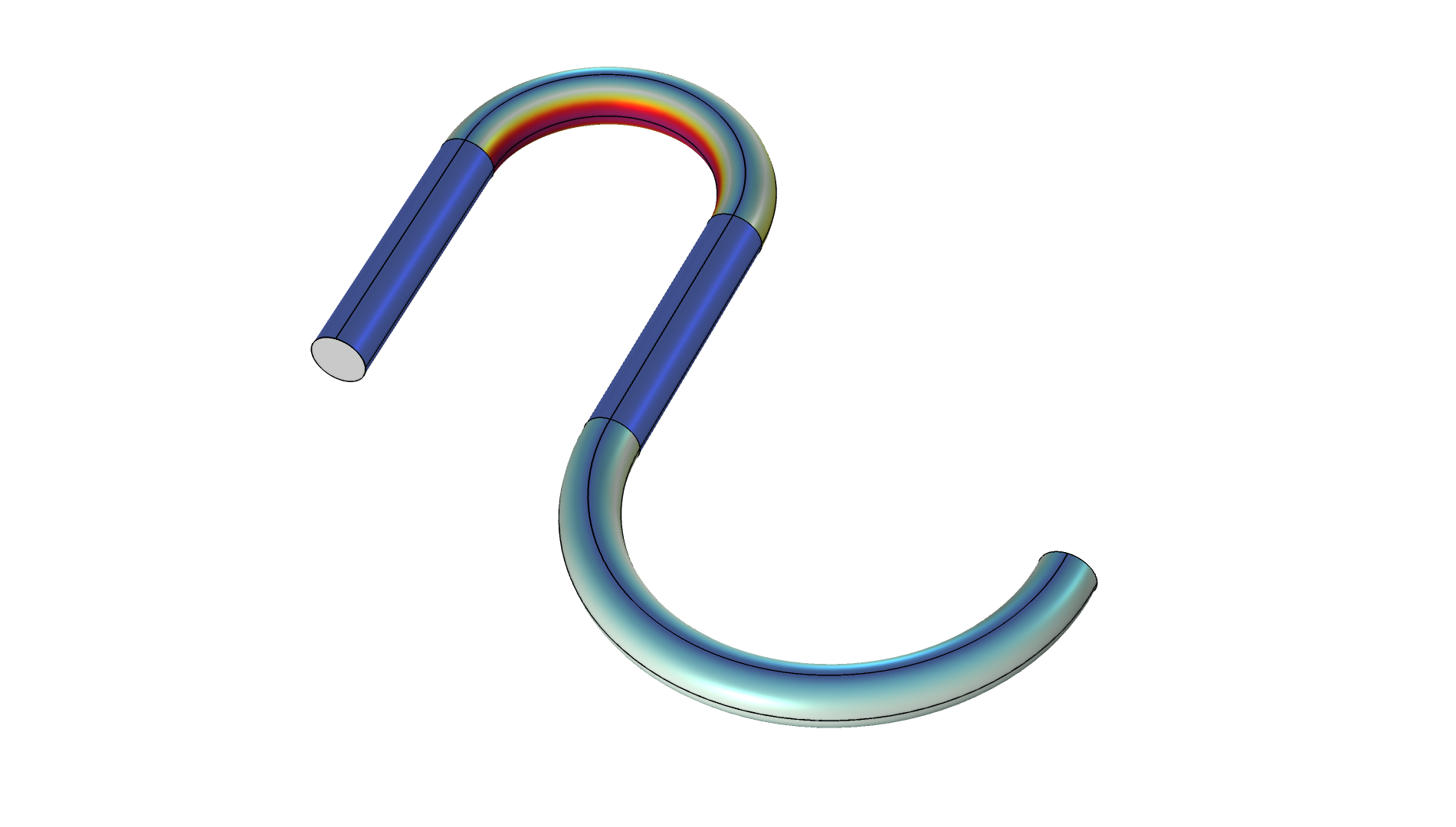 A graphic of a cylindrical geometry curved into an S shape, where the bottom curve is larger and the top curve is tighter, forming an inverted U shape.
 A graphic of a cylindrical geometry curved into an S shape, where the bottom curve is larger and the top curve is tighter, forming an inverted U shape.
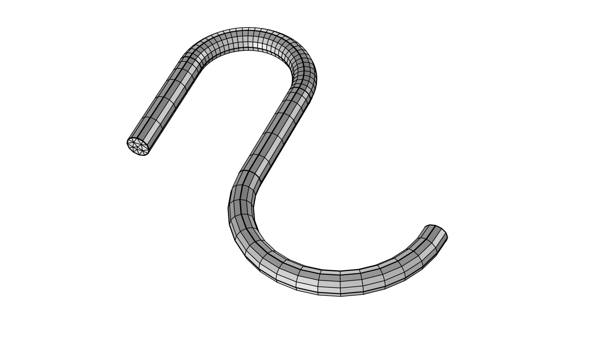 A graphic showing a swept mesh of a cylindrical geometry curved into an S shape that used a Size node to incrementally change the mesh size according to the varying curvature of the geometry.
左侧图显示了待划分网格的几何体的 平均曲率 。中间图先对顶部边链进行网格划分,顶部曲线的曲率因子为 0.1,而底部曲线的为 0.2。需要注意的是,网格大小在各个域之间逐渐变化,以实现平滑的过渡。
In the example above, we chose to select Prism in the Mesh Generation menu of the Swept operation Settings window, but in the attached model file for version 6.4, we used the new Hex dominant option.
考虑相邻域
与扫掠网格域相邻的任何域都可以在扫掠前或扫掠后进行网格划分。如果相邻的域在网格扫掠之前已经进行了网格划分,则可以认为已经对面网格进行了网格预划分。
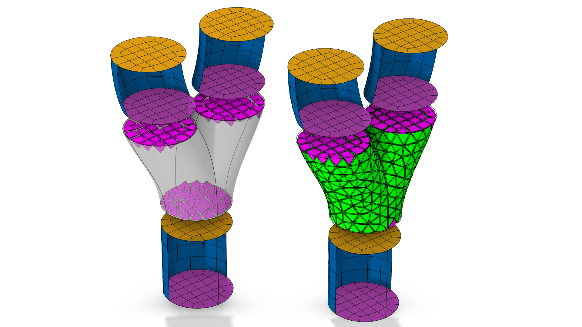
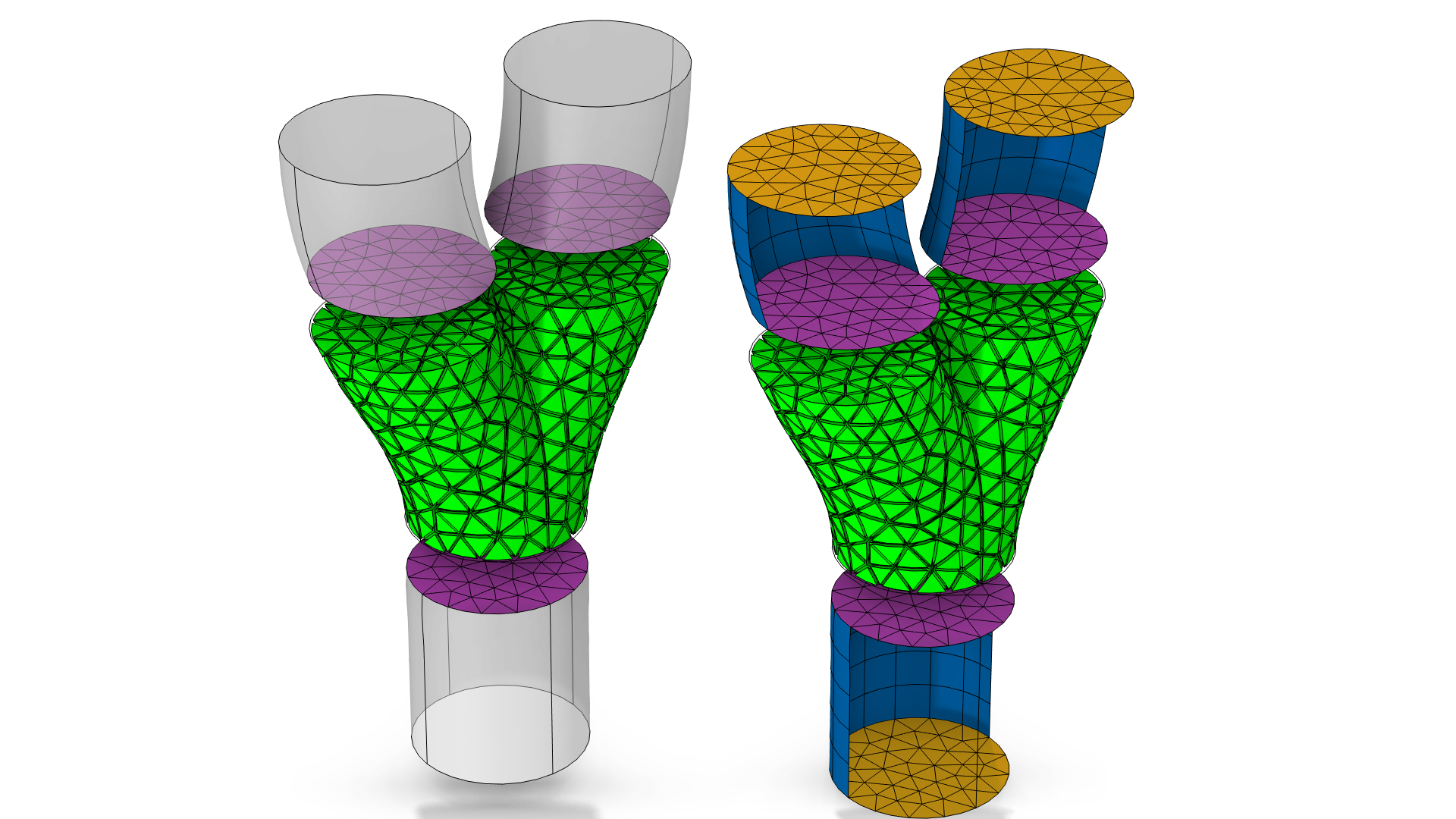
A Y-shaped geometry where the default hex-dominant element is chosen. Notice the difference between building the Swept node before the Free Tetrahedral node (left) and building the Free Tetrahedral before Swept (right). Pyramids (magenta) are inserted to match the hexahedral elements (left) as opposed to the triangles from the tetrahedral elements (green) are used as a source mesh for Swept (right).
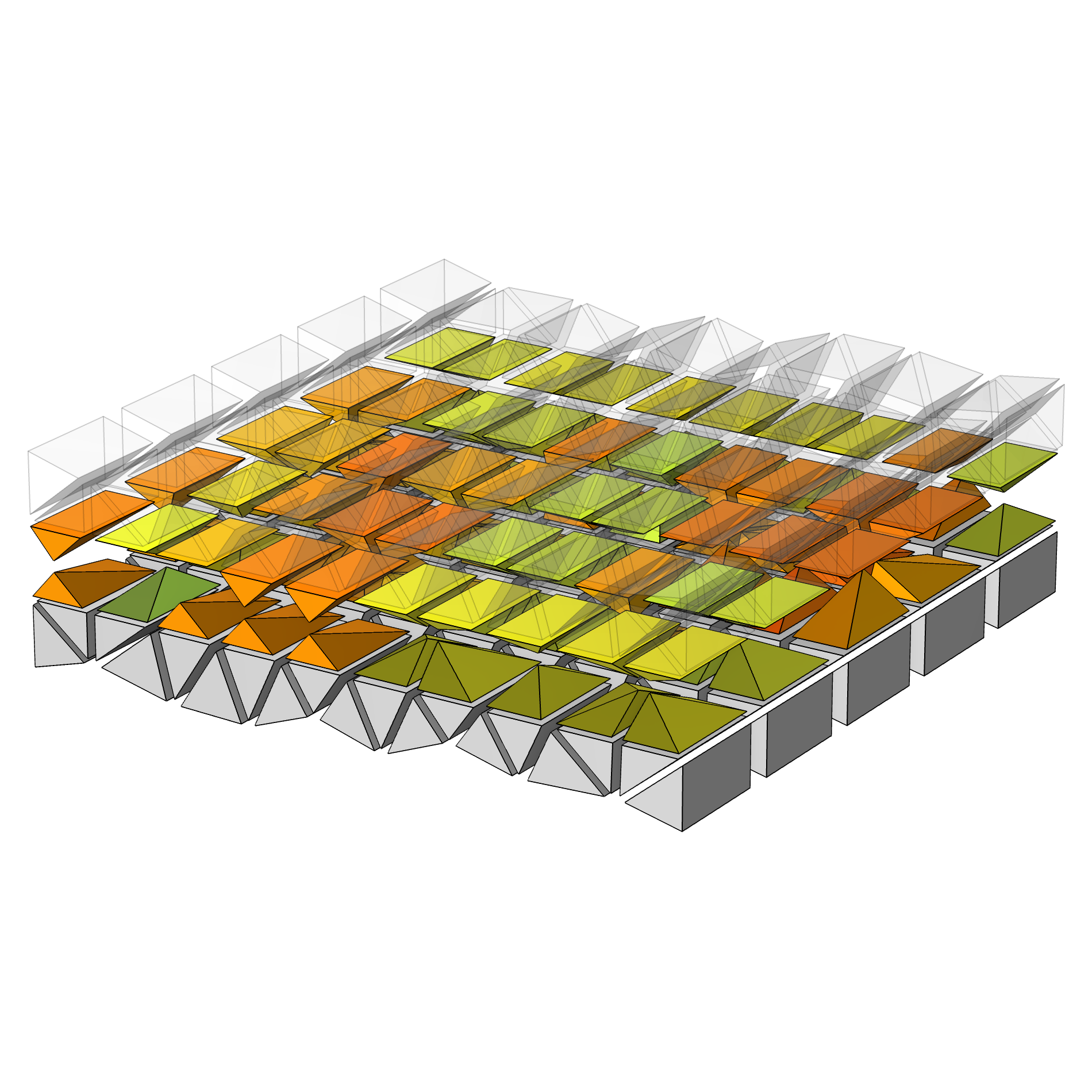
If building a mesh adjacent to the linking faces of a domain with swept mesh, a layer of pyramids (magenta in the animation below) is inserted closest to the linking faces, which enables a transition between the swept mesh elements (yellow quads) and the tetrahedral mesh elements (i.e., green volume mesh elements with only triangular mesh faces) in the surrounding domain. See this blog post for information about creating mesh plots.
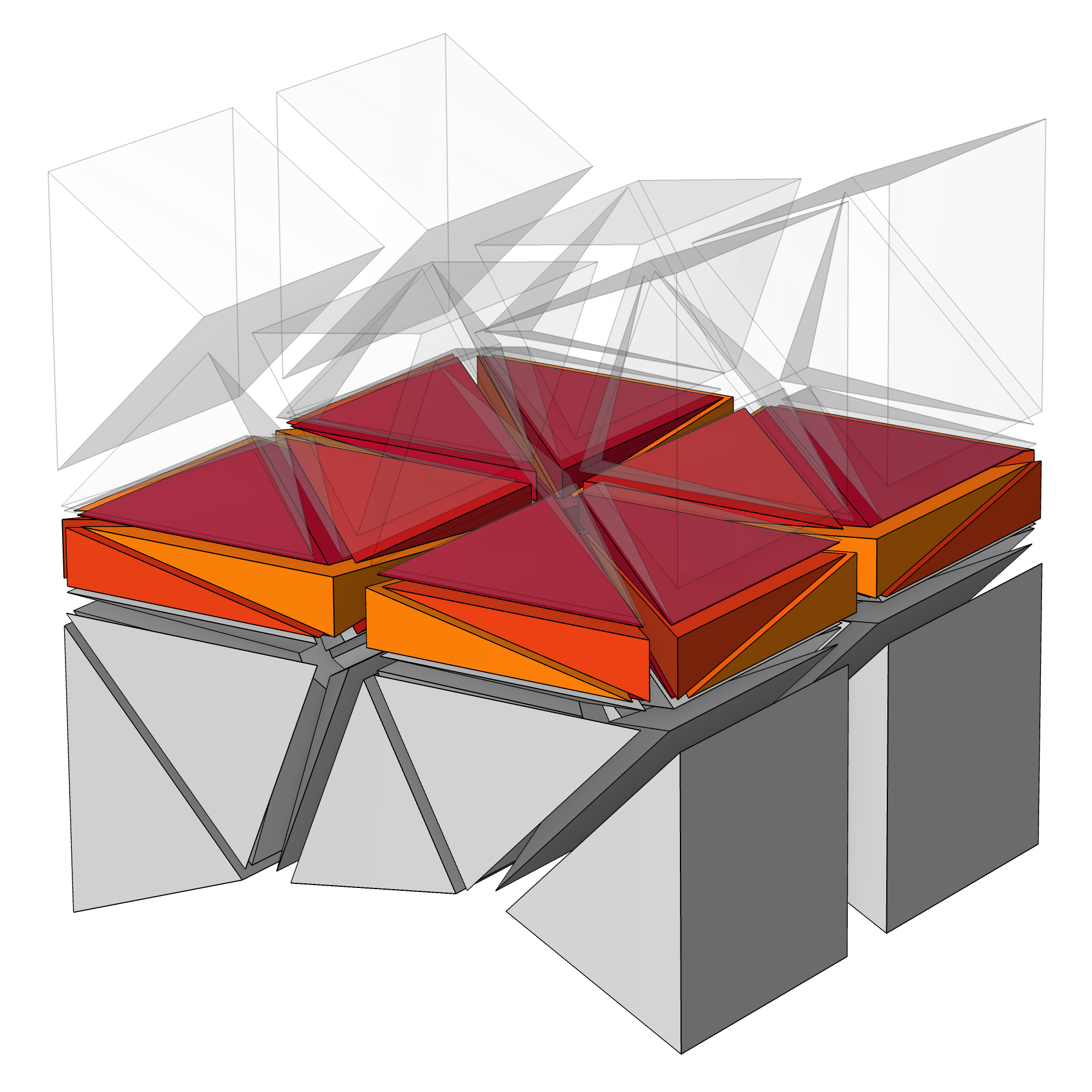
Depending on the number of layers that are inserted along a sweep, the pyramids can become very elongated in one direction which, for some physics, should be avoided.
 A swept meshed cylinder with five element layers, with the skewness quality depicted as green pyramids with relatively high peaks.
 A swept meshed cylinder with one element layer, with the skewness quality depicted as flat orange pyramids.
 A swept meshed cylinder with 100 element layers, with the skewness quality depicted as small orange pyramids.
如果纵横比过大,有以下方法可以提高网格质量:
- 改变网格单元沿扫掠方向的分布,使纵横比更接近 1。这取决于物理场,因为物理场可能会要求网格有一定的分布。
- 对源面进行预网格划分。使用不同的大小设置进行网格预划分,使外边缘的网格更符合扫掠中单元层的分布。
- 如果可能,将周围的域也包括在扫掠范围内。我们将在本课程的后续部分讨论如何分割相邻域。
- 使用 形成装配体 确定几何体的内部关系。虽然网格质量会提高,但在研究过程中可能会产生一些插值误差。点击 此处了解更多信息。
Note that the physics may also set requirements on the mesh. This is not taken into account here.
Even if you take care that the quads have similar side lengths, there are also some things to consider when the adjacent domain has a thin domain region.
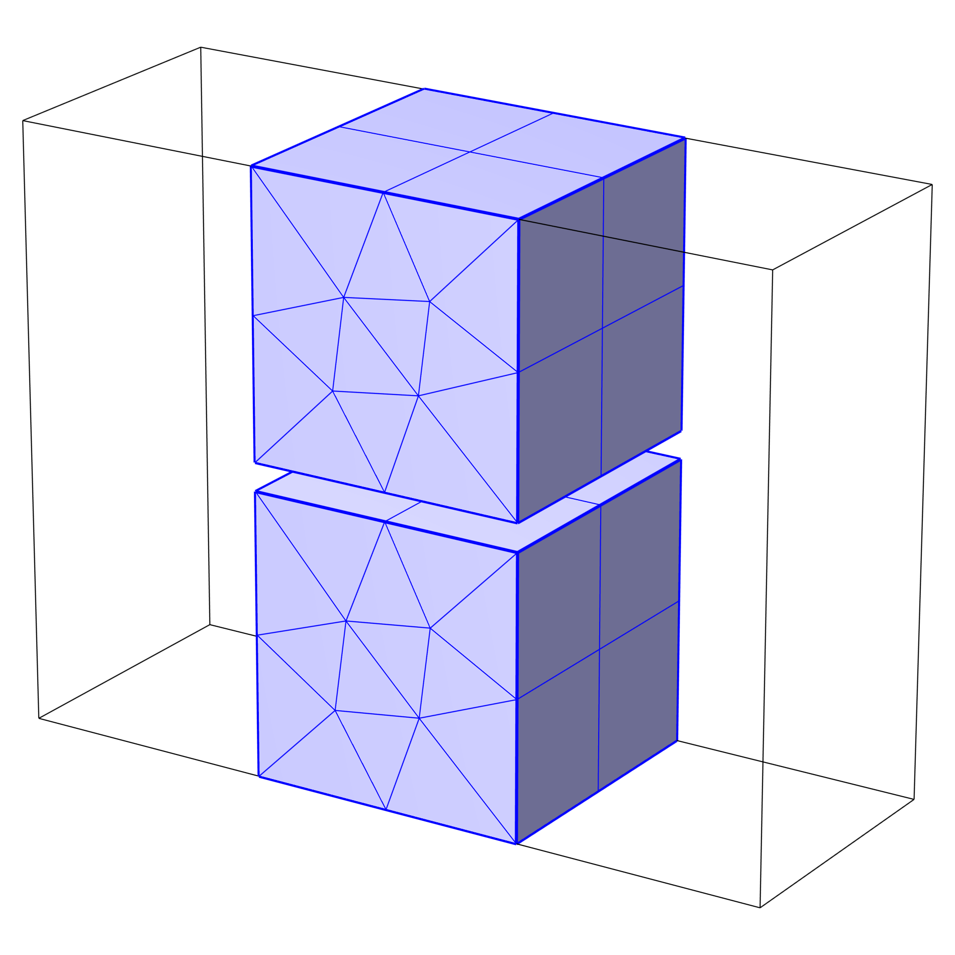 Two identical meshed cubic geometries, one above the other with a thin space between.
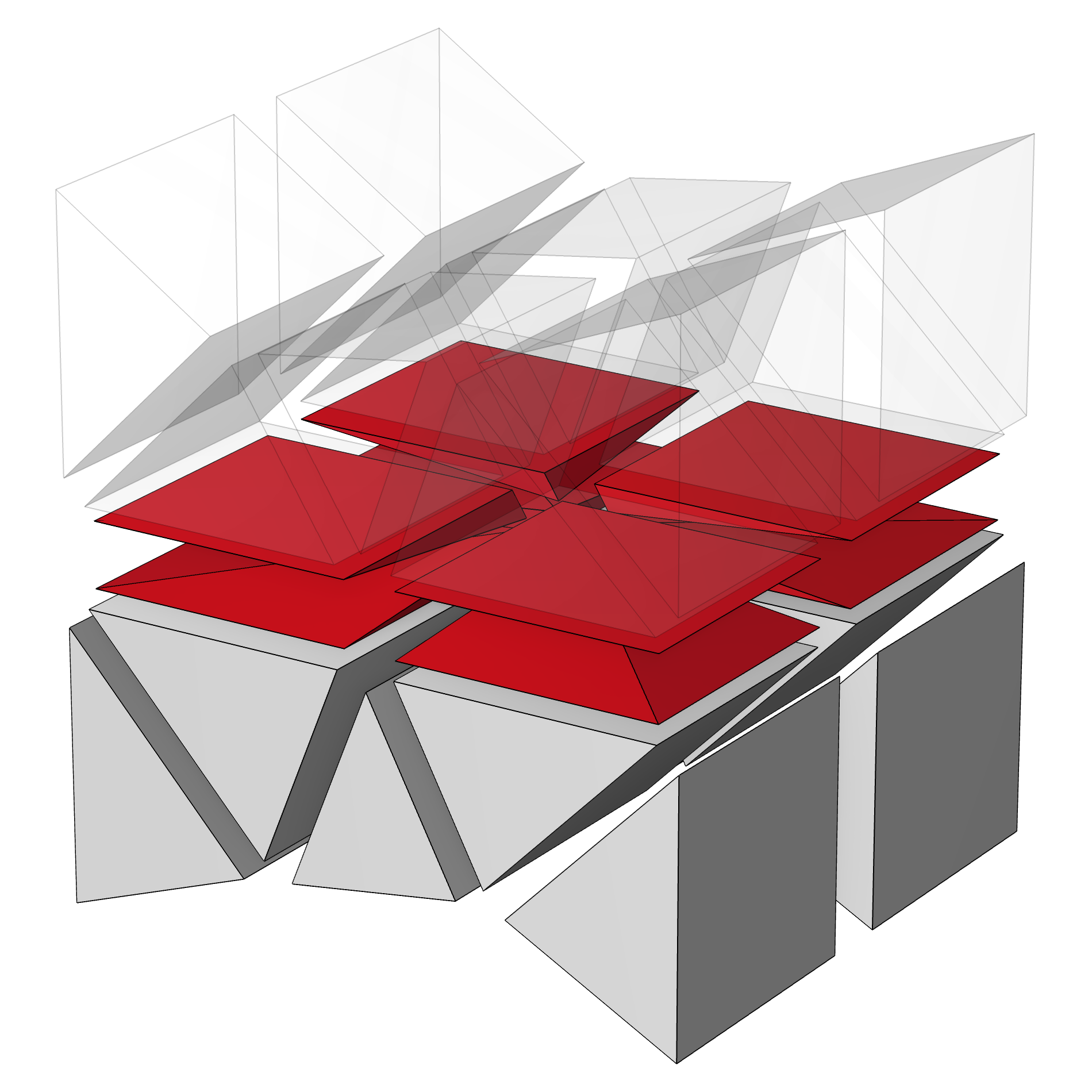 A close-up of the meshed space between the two blocks, showing low quality, flat pyramids.
如果这个薄域表示一个薄层,请考虑是否可以用边界条件取代实体建模。这篇博客对此进行了说明。如果与物理场无关,可考虑使用几何操作折叠狭窄区域。
如果必须包含狭窄区域,一种解决方案是在靠近窄域的源面上细化网格尺寸,并增加单元层数。与之前的情况相比,这将生成更多的网格单元。
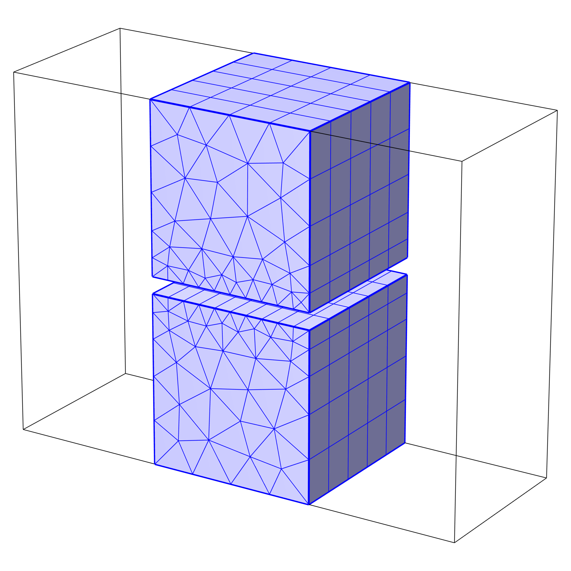 A thin layer of space between two vertically stacked blocks is meshed with a refined size.
 A close-up of the meshed space between two stacked blocks, showing an increased number of mesh elements.
这种处理方法有时需要大量的网格单元才能正确求解小间隙的问题。在某些情况下,您会发现自由四面体网格是更好的选择。
在本示例的几何体中,也可以通过一次扫掠操作将所有域扫掠到一起。这将保证最终网格的质量,因为与金字塔或四面体单元相比,棱柱或六面体单元能更好地处理大纵横比问题。在本课程的后续部分,我们将研究如何修改几何体,以便对域进行网格扫掠。
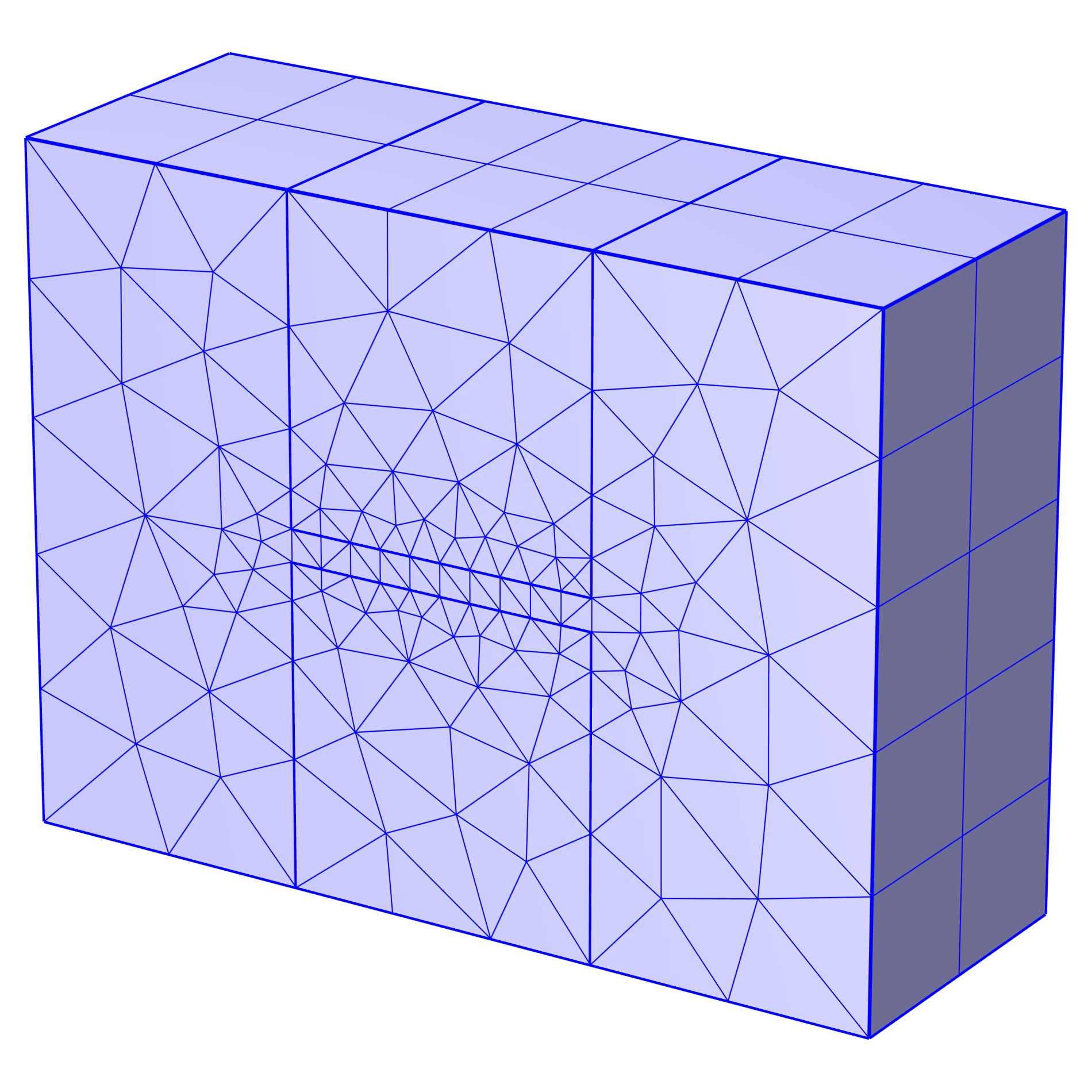 A mesh of several cubic domains all swept together, with prism and hexahedron mesh elements.
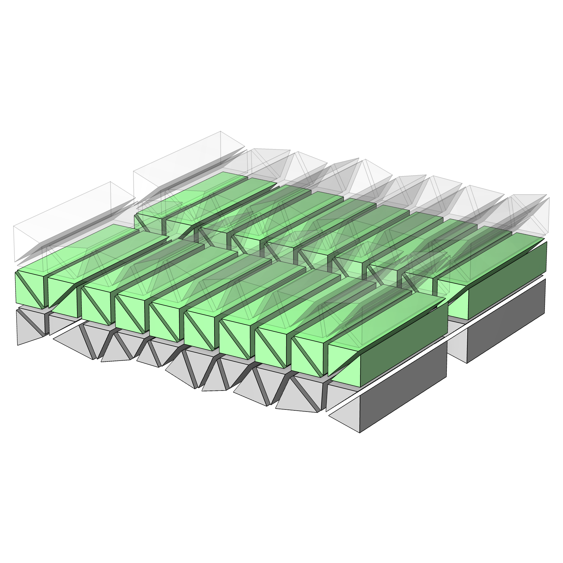 A close-up of the hexahedron mesh of the thin domain included in a sweep of several cubic domains.
最后,如果金字塔单元插入失败,或者想要加快生成 自由四面体 单元的速度,可以使用 转换 操作。通过将四边形单元转换为三角形单元,无需插入金字塔单元即可完成网格划分。不过,这也会分割扫掠网格中的部分单元。考虑到这一点,请务必检查网格质量。
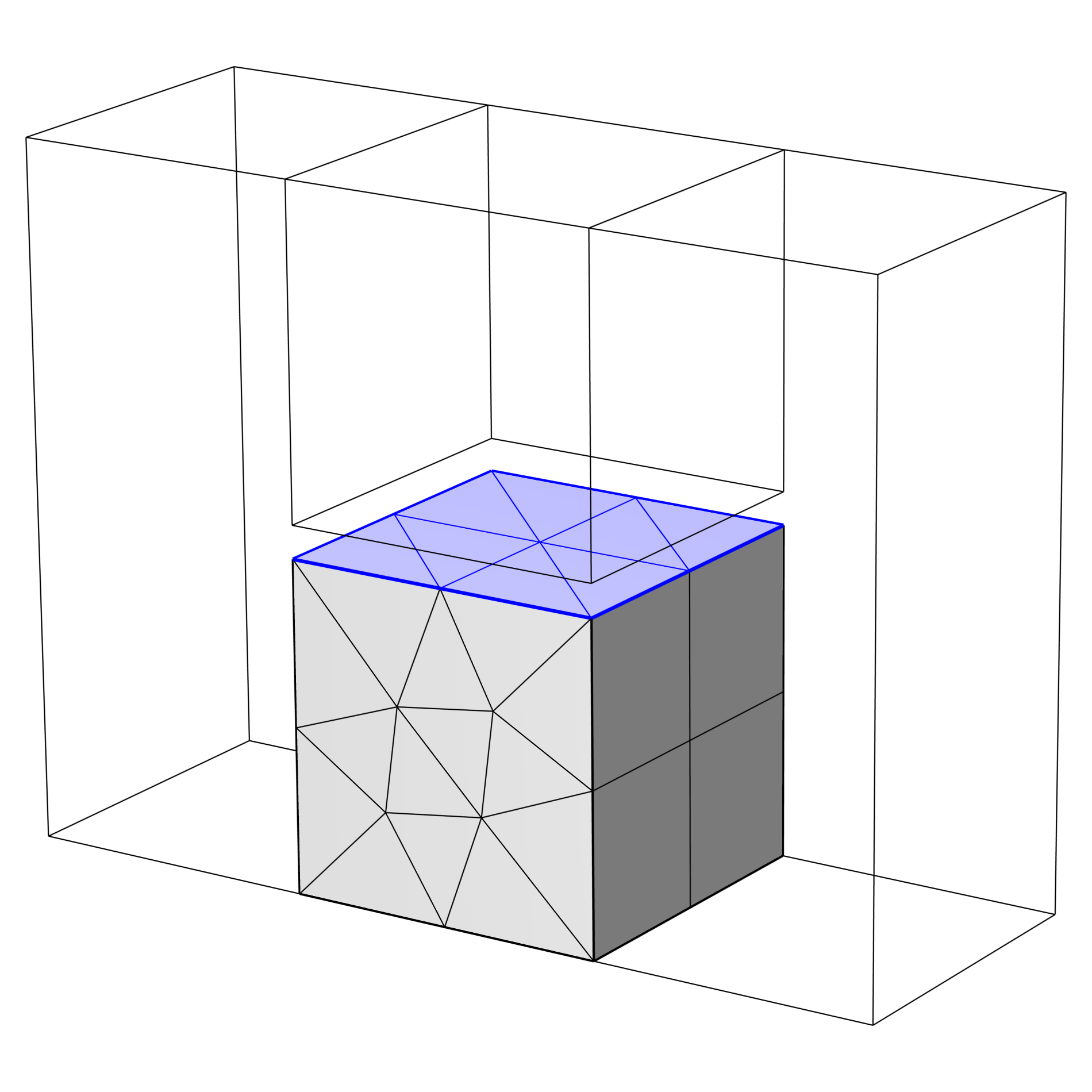 Triangular mesh elements of a thin domain between two stacked blocks, with the top block hidden for visibility.
 A close-up of the low quality tetrahedra that result from converting the mesh elements of a thin domain between two stacked blocks from quad to triangular.
靠近狭窄区域的面由四边形网格单元转换为三角形网格单元(左侧图中隐藏了上方立方体的网格)。这意味着无需在窄域插入金字塔单元,但生成网格的质量不一定会得到改善(如右侧图所示,四面体网格的质量较低。)
进阶学习
本文介绍了几个示例,对生成高质量扫掠网格所需考虑的几个最重要的方面进行了补充。您可以在文章附件中找到这些示例的 MPH 文件,亲自动手操作以了解如何为这几种类型的几何体生成高质量的网格。
请提交与此页面相关的反馈,或点击此处联系技术支持。


