
扫掠网格的术语和要求
在扫掠网格系列课程的第一部分中,我们学习了在哪些情况下可以使用扫掠网格。在第二部分中,我们将深入探讨扫掠 操作的一些细节,包括扫掠网格的术语,以及何时可以使用扫掠操作。
扫掠网格的术语
首先,我们从介绍 COMSOL Multiphysics® 中有关扫掠网格的一些术语开始。扫掠网格所划分的域上的面被分为源面、目标面或链接面。扫掠操作从源面开始,到目标面结束,以此来定义扫掠方向。链接面连接源面和目标面。
链接边 是指与扫掠方向近似相切的边(或边链)。截面边 是指近似垂直于扫掠方向的边(或边链)。
截面边可能会围绕某个域形成闭合环路,在这种情况下,由两个这样的环路所围成的链接面就被称为截面。
请注意,截面可能还包含一些额外的孤立面,比如下图中看到的小矩形面。
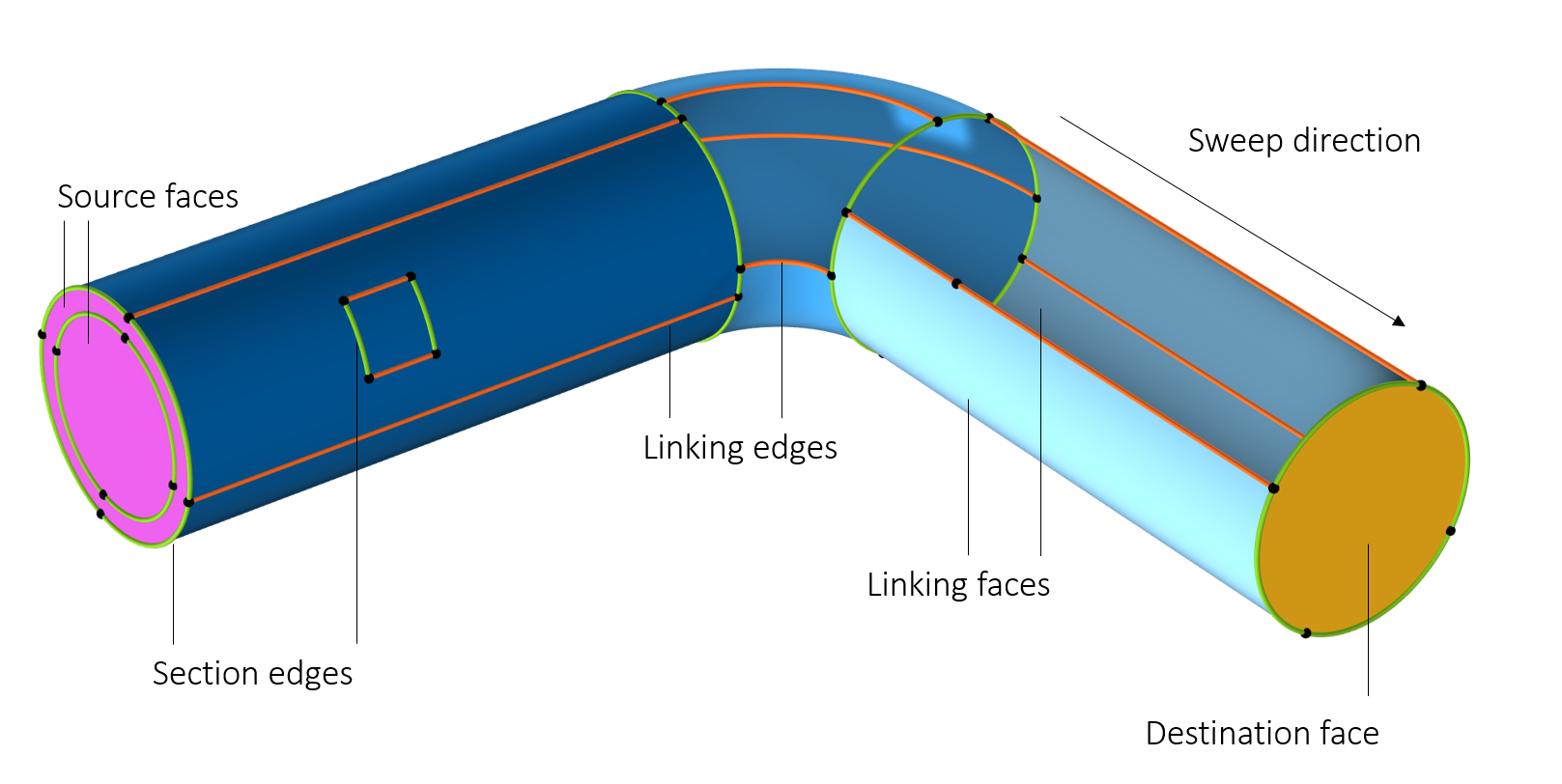
扫掠网格划分的域上的边界和边的分类。截面用三种深浅不同的蓝色表示。隐藏了两个面以显示域的内部。
扫掠网格的要求
在尝试生成扫掠网格之前,第一步是确保目标域符合此文档中描述的几项标准。由于在几何体中选中扫掠的每个域都遵循相同的逻辑,因此我们将在本课程中重点讨论一个域。这个域符合下述 4 条标准:
- 域中不包含孔、孤立面或空隙
- 源面和目标面必须是连续的面分量
- 每个目标面必须对应一个或多个源面,而每个源面必须精确对应一个目标面或其子集
- 每个截面必须至少有两条连接边或边链
我们将详细探讨上述每一项要求,因为本列表中一些技术性问题被刻意回避了。如果不符合其中任何一项要求,都可能出现错误信息。在后续第三部分课程中,我们将介绍解决这些以及其他潜在问题的技巧。
由于几何选择中所有将要进行扫掠操作的域均遵循相同的逻辑,因此在这里我们将仅针对其中一个域展开说明。
对域的形状的要求
处理孔、孤立面和空隙
域中不允许有孔、孤立面或空隙。唯一的例外情况是,孔或孤立面同时穿透源面和目标面,如下图所示。
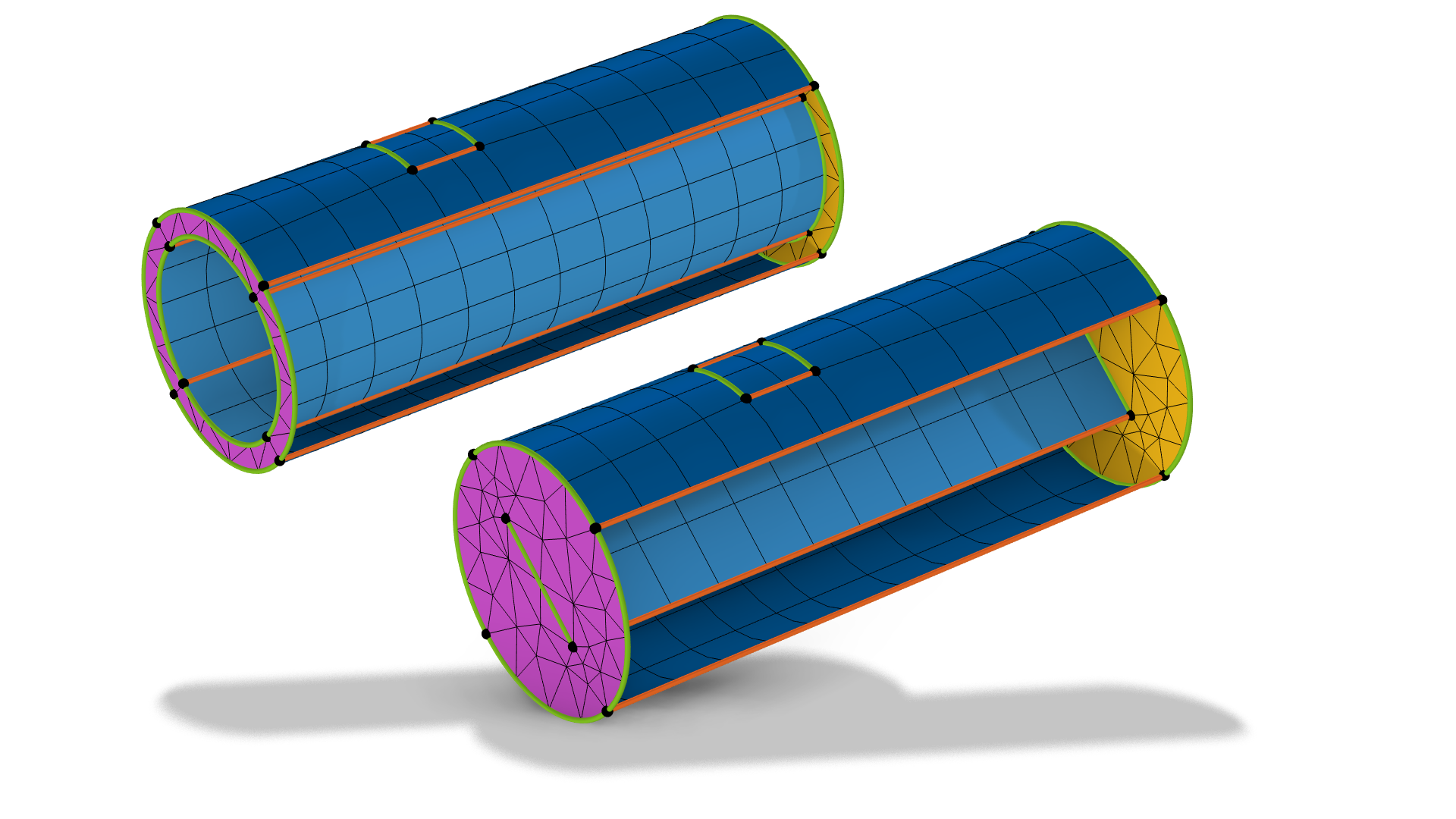 Models with domains that include a hole and face that penetrate both the source and destination of the swept mesh.
包含孔和孤立面的域。左图:由于孔和面都穿透了源面和目标面,因此这些域是可扫掠的。请注意,含孤立面的域可以进行网格扫掠,因为其内部边界可以进行网格映射,并遵循扫掠的大致方向。
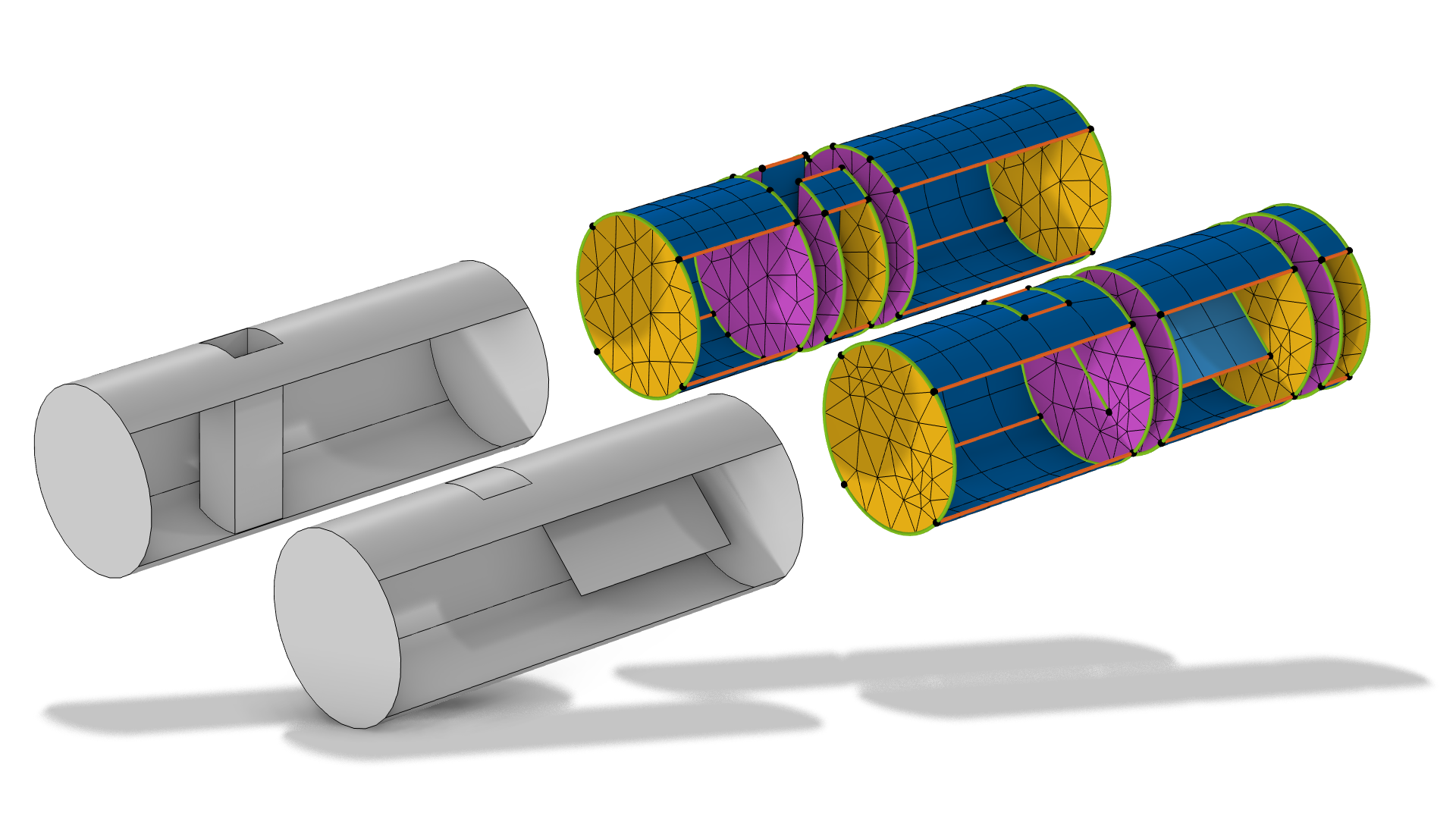 Models with domains that can be swept if they are first partitioned.
左侧的域可以被划分为多个更小的可扫描域。
该域存在一个贯通源面和目标面的孔,因此可以生成扫掠网格。该孔可沿扫描路径移动并改变大小,网格也会随之发生变形。请注意,变形后得到的最终网格可能包含畸变单元,这些单元通常并不适用于仿真计算。
此外,, 若域具备几何厚度,且源实体与目标实体之间存在一一映射关系,则域可以包含空洞区域,如下图所示。
 A shell with a void inside.
 The void region show with a clip plane.
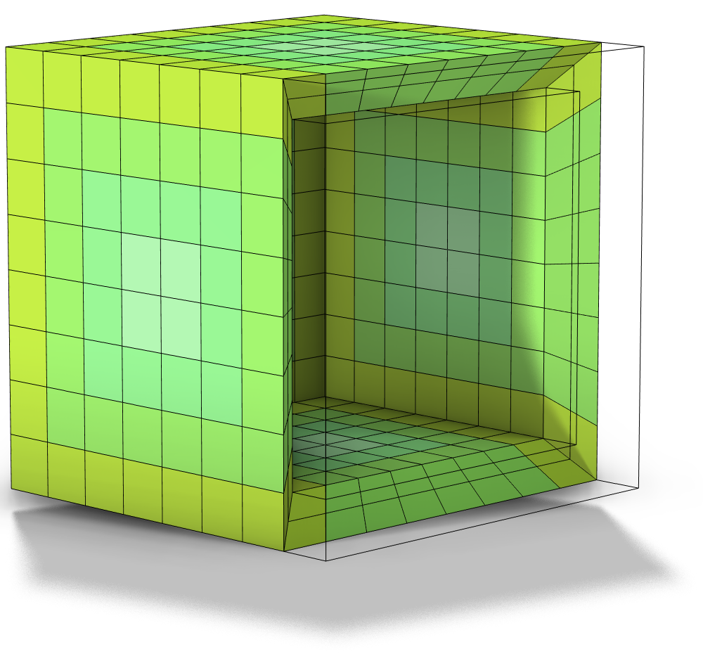 A plot of a swept mesh.
从左至右:1)一个内部含有空洞区域的壳域。2)通过剖切平面展示的空洞区域。3)扫掠网格的图示,为便于观察,部分单元已被过滤移除。
如何将源面和目标面连接到域
现在我们来看第二条规则。对于每个域,目标面必须是连通的面组件;从 6.4 版本开始,源面可以为非连通的面组件。从域层面理解该规则的另一种方式是:域内可以包含“台阶”,使源面位于扫掠方向上的不同高度位置。如果几何模型在扫掠的两端均存在台阶,可尝试将域切分为多个能够进行扫掠划分的小区域(见下方钢管图示),或将扫掠网格与自由四面体网格结合使用。
请注意,只要源网格与目标网格保持一致(包括面的所有扭转情况),源面与目标面重合是允许的,具体可参见下方钢管几何体的动画所示。
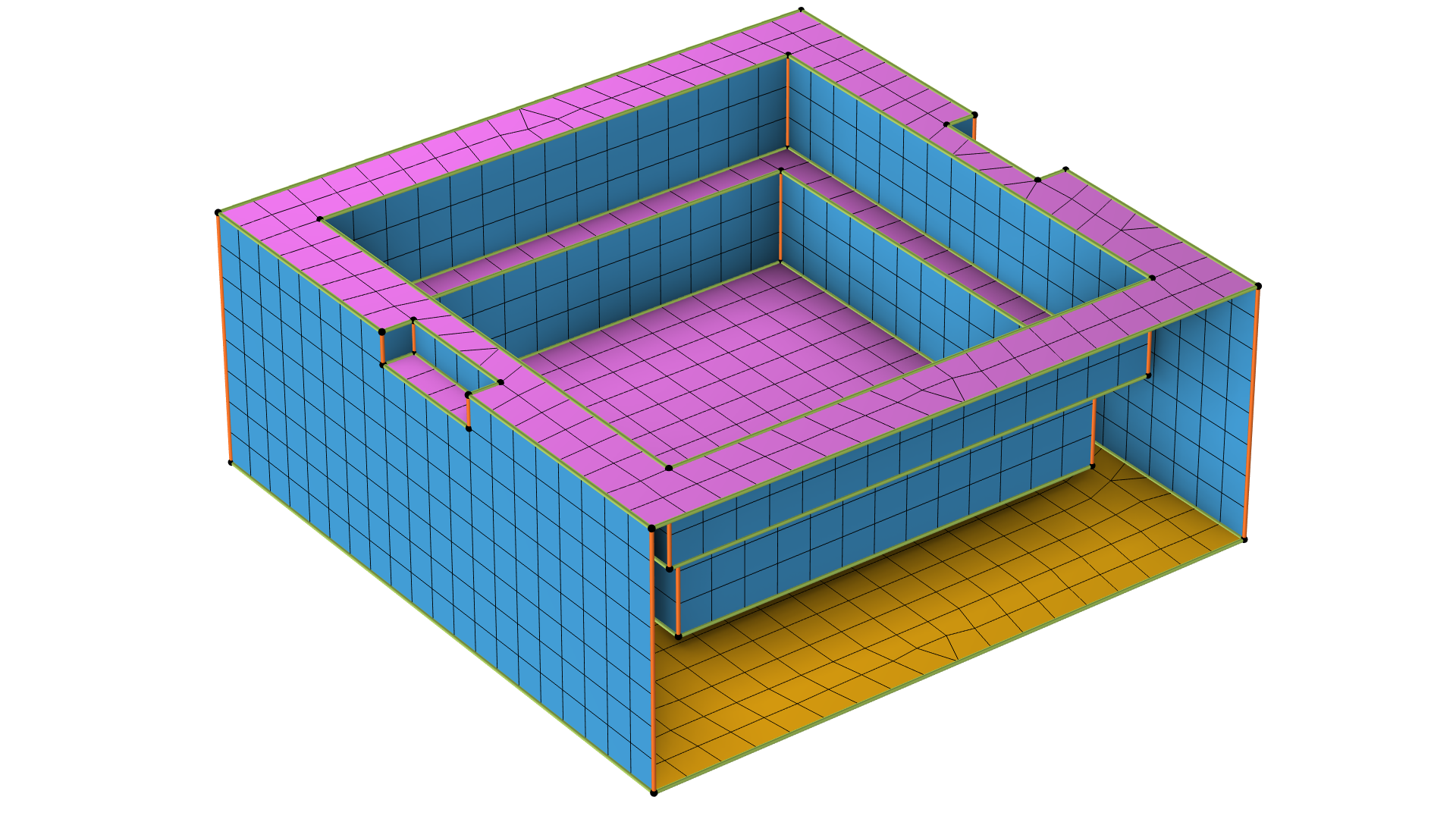 A rectangular 3D geometry with the faces shown with mesh elements.
从 COMSOL Multiphysics® 6.4 版本开始,该域可自动进行扫掠网格划分。源面(洋红色)属于非连通组件,因为它们处于不同高度;而底面,即目标面,为连通面组件(黄色)。
A rectangular 3D geometry with the faces shown with mesh elements.
从 COMSOL Multiphysics® 6.4 版本开始,该域可自动进行扫掠网格划分。源面(洋红色)属于非连通组件,因为它们处于不同高度;而底面,即目标面,为连通面组件(黄色)。
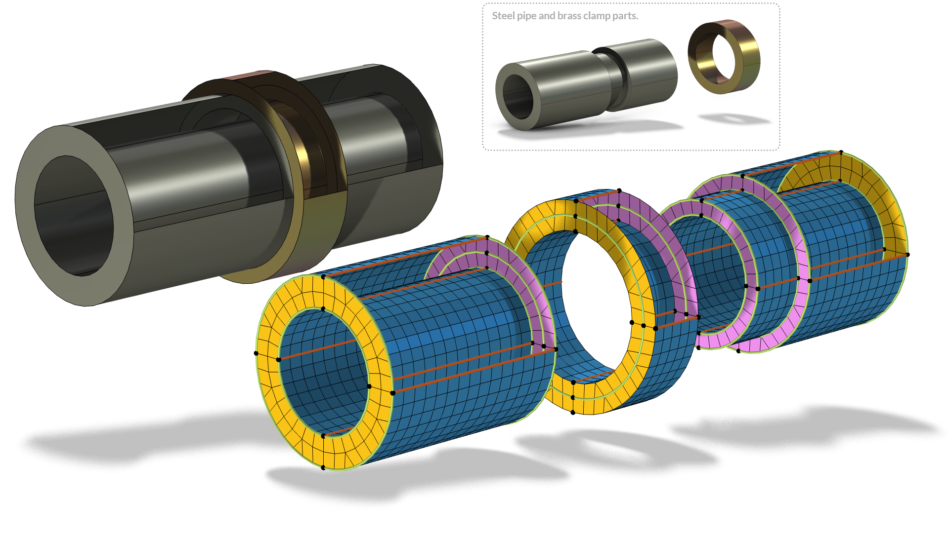 A domain with disconnected face components. A cylindrical 3D geometry is shown assembled, in parts, with the faces colored in yellow, magenta, and blue and mesh elements applied.
左侧钢管为单个实体域,黄铜卡箍所在位置存在一处凹口。通过使用与卡箍侧面平行的工作平面对该钢实体域进行分割,即可对整个几何模型执行扫掠网格划分(右侧为爆炸视图)。
A domain with disconnected face components. A cylindrical 3D geometry is shown assembled, in parts, with the faces colored in yellow, magenta, and blue and mesh elements applied.
左侧钢管为单个实体域,黄铜卡箍所在位置存在一处凹口。通过使用与卡箍侧面平行的工作平面对该钢实体域进行分割,即可对整个几何模型执行扫掠网格划分(右侧为爆炸视图)。
对扭转环进行的正方形截面网格划分,由于几何体存在半圈扭转,源的表面网格需要具备 180° 的旋转对称性。
可视化扫描路径
在脑海中沿着网格的横截面想象扫掠过程通常会很有帮助。对前两条规则可以理解为:域的横截面必须与目标面相匹配,这与源面和目标面的要求这一章节中描述的一致。例如,如果几何体上有个孔,截面就会出现一个空洞;如果域发生了分岔,截面就会分裂成不连通的几个面。比如下方的 Y 形几何体,其横截面就分裂成了两个互不连通的面。关于如何切分几何体以便对局部域进行扫掠划分,请参考 “如何控制扫掠网格”中介绍的示例。
左侧动画直观地解释了为什么这个 Y 形域在进行扫掠网格划分前需要进行切分。右侧动画则展示了用于可视化的部分网格:若通过截面对该计算域进行了分割,该区域本可以生成扫掠网格,但实际上在未切分的情况下,这里并不会生成任何网格。
可帮助实现上述可视化的一个方法是,添加一个与扫掠横截面平行的剪裁平面 ,然后沿扫掠方向拖动剪裁平面的边框。请确保选中了显示横截面选项。
这段视频演示了如何从图形窗口手动查看扫掠路径。由于该域包含一个空白域,这一点在扫掠路径的中段表现得尤为明显,因为此时截面变成了中空状态。因此,这个域需要被分割为三个部分,并在中间域上采用四面体网格,域上述 Y 形几何结构类似。
孤立实体的特殊示例
孤立边和孤立顶点是指位于域或面内的边和顶点,它们不属于任何一个用于划分面的孤立实体。当存在孤立边和孤立顶点时,会先生成网格,这一过程不考虑这些孤立实体。然后在第二步,通过移动附近的一些网格节点,将这些孤立实体纳入处理,并“黏合”到现有网格中。在扫掠过程中,网格会适配这些孤立实体。
如果不需要这些孤立实体,可以考量使用虚拟操作将其从几何体中移除。更多信息请参阅这篇 博客文章。
 The interior of a mesh with and without isolated entities on the linking faces..
域内无(左)或有(右)孤立实体的内部可视化网格。右图中的网格发生了扭曲,以便在扫掠过程中适配孤立的实体。
源面和目标面的要求
每个目标面必须对应一个或多个源面,而每个源面必须精确对应一个目标面或其子集。换句话说,源面可以包含比目标面更多的面,只要能够将网格映射到目标面上即可(允许一定程度的变形,就像我们在这个动画中看到的那样)。
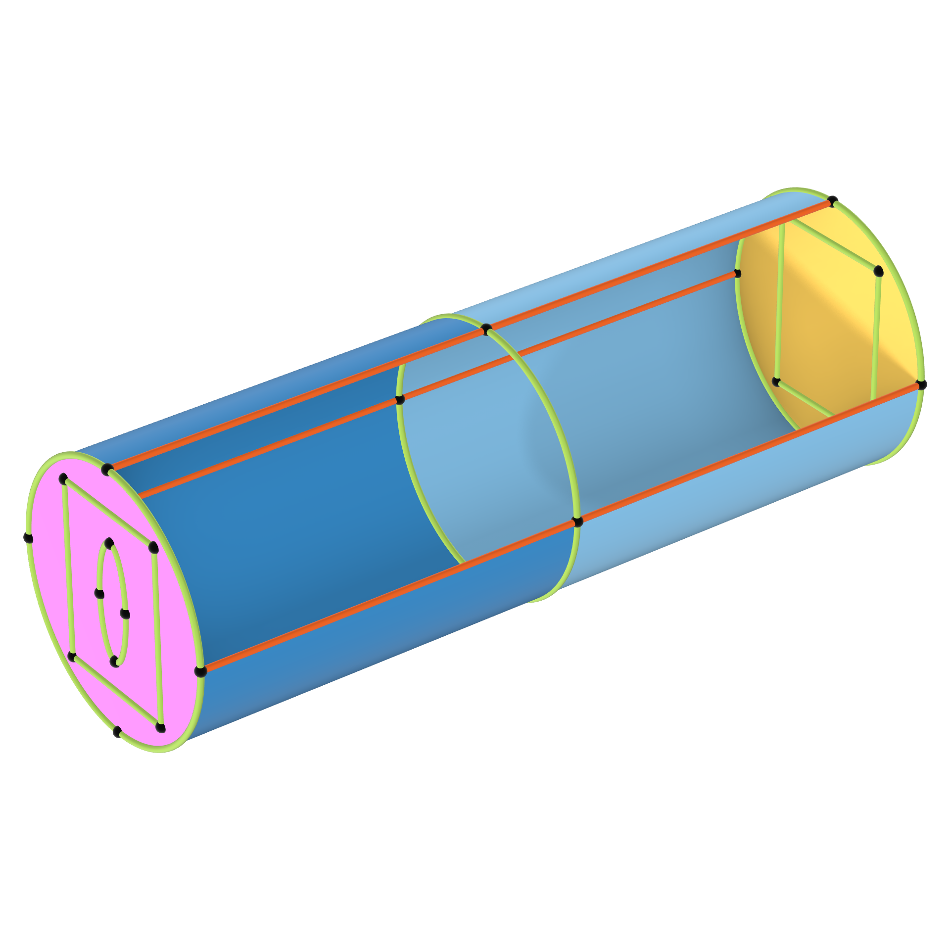 A geometry with more source faces than destination faces.
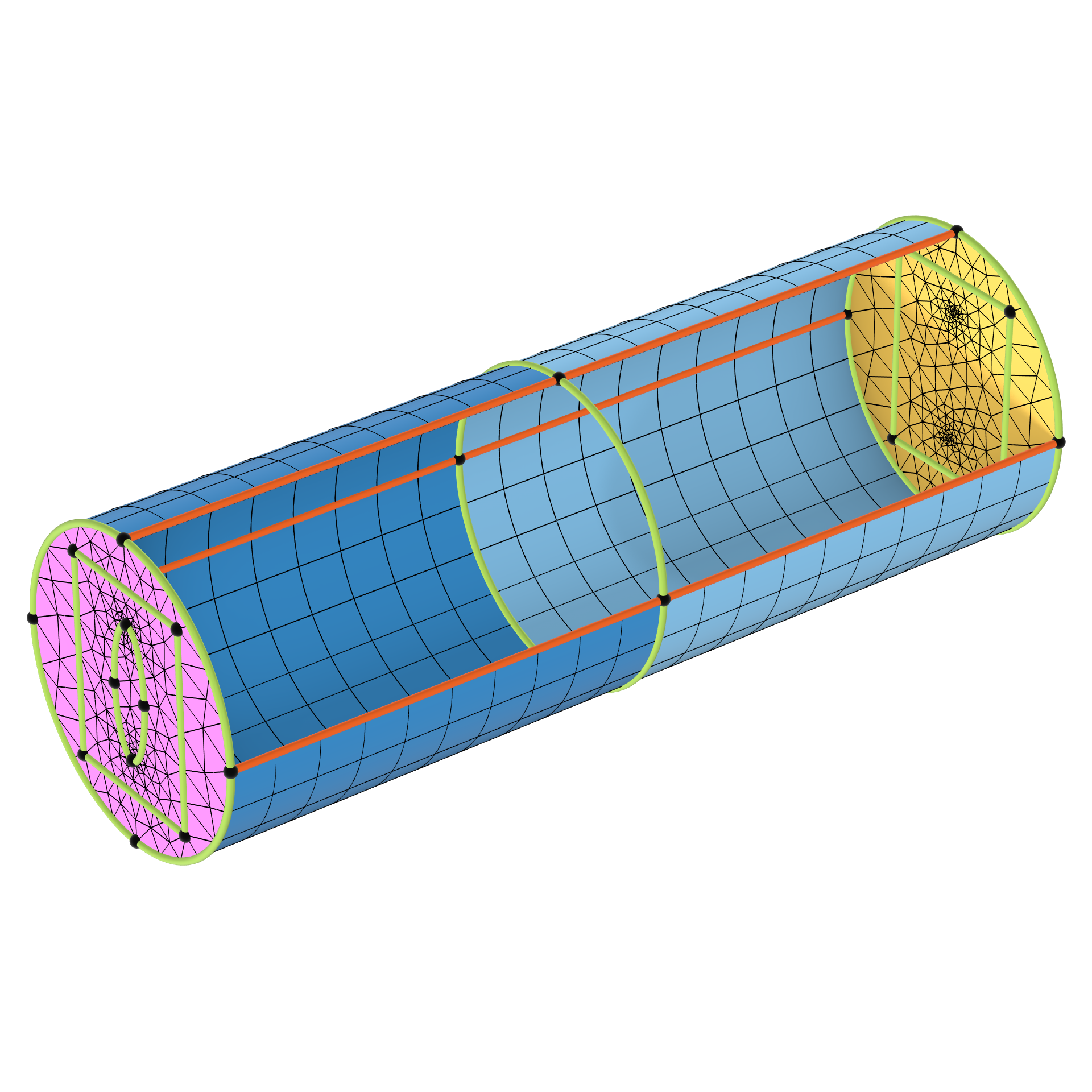 A meshed geometry with more source faces than destination faces.
尽管源面(洋红色)多于目标面(黄色),但该几何体仍可进行扫掠网格划分。
大多数情况下,源面和目标面之间不存在变形,只需对源面进行平移和旋转,使其与目标面重合即可。在这种情况下,我们可以在头脑中想象将源网格复制到目标网格,查看复制操作是否可行。下面的动画演示了这种想法的可视化过程。
图中只显示了源面和目标面,颜色与上一个三维视图相同。请注意,源面比目标面多,每个目标面对应一个或多个源面。
不符合此规则的示例:由于目标面较多,因此无法复制网格。网格复制失败的边用红色高亮显示。因此,对于之前的三维几何结构,扫掠方向无法反转。
将源面的部分边投影到目标面上,或者反过来操作,是解决域内源面与目标面不匹配的一种策略。同时,这种做法也能确保扫掠过程中生成的网格是相互匹配的。后一种情况如下图所示。
 A cylindrical gray 3D geometry has two domains, which are also shown separately on the right, with the mesh elements and faces colored in magenta, blue, and yellow.
包含两个域的几何体,通过将矩形边投影到中间面上,可以使整个几何体满足扫掠网格的生成条件。否则,就无法保证从顶部向中间扫掠,与从底部向中间扫掠所生成的网格保持一致。
A cylindrical gray 3D geometry has two domains, which are also shown separately on the right, with the mesh elements and faces colored in magenta, blue, and yellow.
包含两个域的几何体,通过将矩形边投影到中间面上,可以使整个几何体满足扫掠网格的生成条件。否则,就无法保证从顶部向中间扫掠,与从底部向中间扫掠所生成的网格保持一致。
更多投影操作的示例,请参见此处。
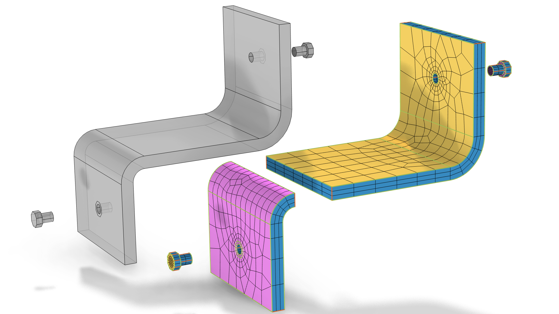 3D geometries of a gray, angled bracket and bolts are shown on the left, and the same geometry is shown on the right, with mesh elements applied and the faces colored in magenta, blue, and yellow.
要对上图带有螺钉印记的的角钢进行扫掠网格划分,可以将计算域切分为两部分(右图),而不是直接把螺钉印记投影到几何体上。请注意:即便这两个计算子域的扫掠方向相反,该几何模型仍可通过一次扫掠操作完成扫掠网格划分。
3D geometries of a gray, angled bracket and bolts are shown on the left, and the same geometry is shown on the right, with mesh elements applied and the faces colored in magenta, blue, and yellow.
要对上图带有螺钉印记的的角钢进行扫掠网格划分,可以将计算域切分为两部分(右图),而不是直接把螺钉印记投影到几何体上。请注意:即便这两个计算子域的扫掠方向相反,该几何模型仍可通过一次扫掠操作完成扫掠网格划分。
链接边的要求
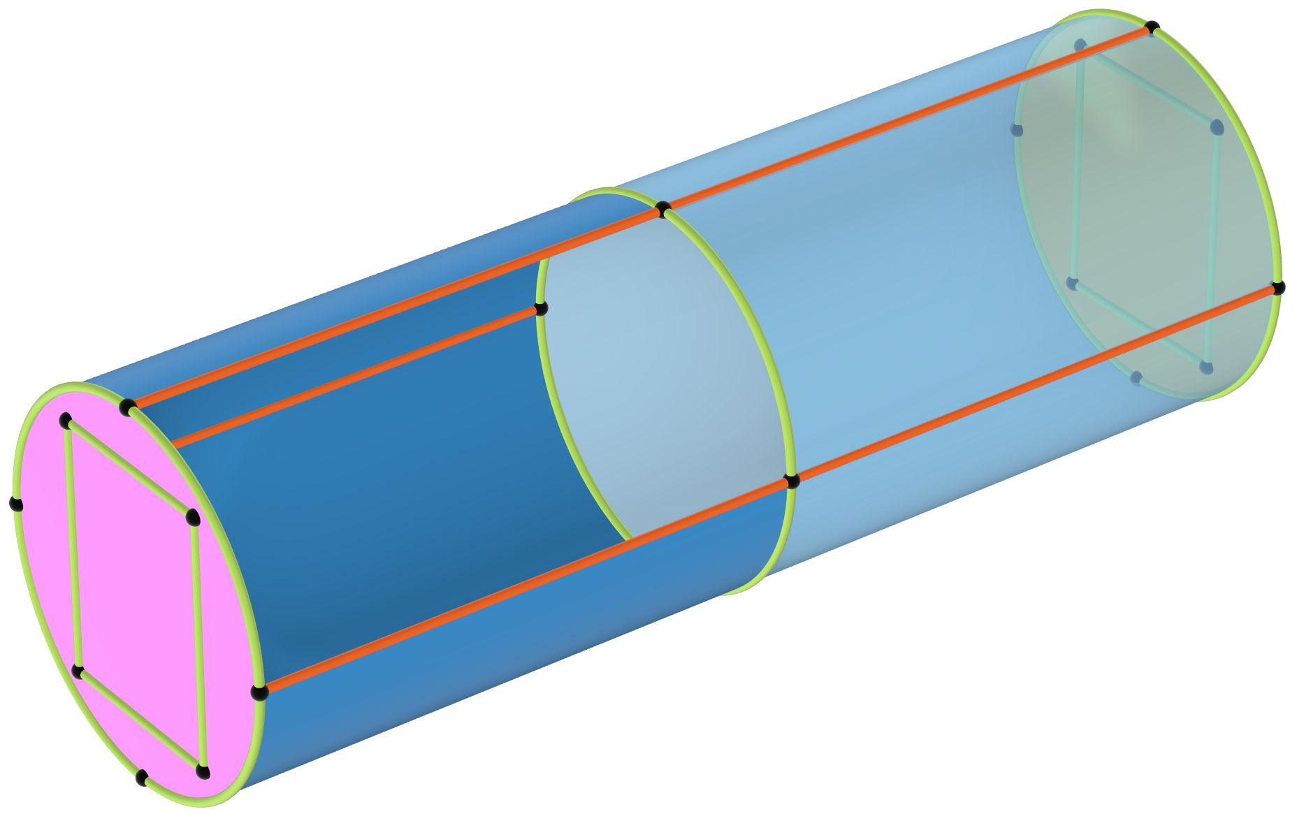
每个截面必须至少包含两条链接边。对这一规则的另一种解释是,每个截面至少应对应两个链接面。
 A domain with linking edges that can be swept meshed.
该几何域可以执行扫掠网格划分,因为两个截面(深蓝与浅蓝色)均至少存在两个链接面。
A domain with linking edges that can be swept meshed.
该几何域可以执行扫掠网格划分,因为两个截面(深蓝与浅蓝色)均至少存在两个链接面。
结束语
在本文中,我们讨论了如何辨别哪些几何域适合使用扫掠网格划分,并总结了四条简单的检查规则。如需了解文中介绍的几个示例模型的扫掠网格是如何生成的,请查看本文随附的 MPH 文件。在扫掠网格系列课程的第三部分,我们将介绍生成高质量网格时需要考虑的最关键要素。
请提交与此页面相关的反馈,或点击此处联系技术支持。


