SpaceX Hyperloop Competition: Design and Manufacturing of A Carbon Fiber Composite Chassis for the 2019 Epfloop Prototype Using COMSOL Multiphysics® Composite Materials Module
The EPFLoop team from Ecole Polytechnique Fédérale de Lausanne has developed a capsule thanks to which it achieved 3rd place in SpaceX’s Hyperloop Pod Competition in 2018. This year the EPFLoop team has been selected again to participate at the 2019 Competition held at the SpaceX facilities in Hawthorne (USA - California).
A critical aspect in the design of the new pod has been the choice of embedding chassis, pressure vessel and aeroshell in one compact system. The carbon fiber-epoxy composite structure should be lightweight and withstand load conditions at high acceleration and deceleration as well as presence of vibrations. After successful finite element analyses of the the structure at critical loads, the team manufactured the composite chassis in-house.
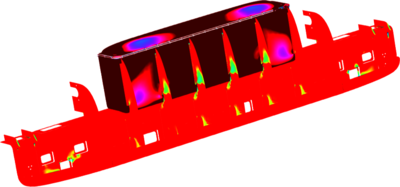
The strength of the structural components was studied under stationary loads using the Composite Material Module, which enables an accurate and easy definition of layered materials, in this case plies of carbon fiber-epoxy and foam. The load cases of maximum acceleration and deceleration considers the weight and inertia of internal component such as batteries, linear induction motor, and the internal pressure of 1 bar. The aim was to design the plies layering to guarantee a minimum safety factor of 2 everywhere, and of 3 for the pressure vessel, as specified by SpaceX requirements. The safety criterion used was Tsai-Wu, which takes into account both in-plane and out-of-plane stresses and is used in the case of orthotropic composites. Other important quantities to be taken into account are shear stresses, principal stresses and displacements. The Composite Material Module made it possible to visualize these quantities at different height in the layup and for each ply, making the analysis all the more thorough.
The vast majority of the structure being thin-walled, a shell model was used to represent it. The initial CAD design being in 3D, was simplified using the Design Module to transform the walls to 2D surfaces. The only solid parts of the model are the junctions between perpendicular composite panels, which are reinforced with a block of epoxy resin. These elements have been created using the Design Module and are included in the Solid Mechanics interface. In order to properly interface both the solid and shell elements, and hence evaluate the stresses occurring at these junctions, the Solid-Shell Multiphysics coupling was used.
Using the aforementioned interfaces and solutions, the structure was optimized to be the lightest possible while resisting to all the applied static loads with the imposed safety factors. Multiple iterations of finite element analysis were carried out on the layers to use, and each section of the pod was finally assigned to its specific layup. Structural integrity was confirmed by testing of the PV with a pressure difference applied between the inside and the outside, and by testing of the chassis during several runs of the pod.