如何基于三维模型的横截面创建二维几何结构
COMSOL Multiphysics® 软件包含了许多专门用于创建特定类型几何的功能,例如,通过使用平面切割实体从三维对象创建二维几何。在这篇文章中,我们将讨论一些应用了这些功能的示例,介绍这种方法的优势,并演示如何操作。
应用示例和功能
从三维几何中提取一个横截面,然后在二维模型中使用该横截面,这在构建涉及以下任何要素的模型时都特别有用:
- 对称或轴对称三维几何,可以基于三维模型创建二维模型,大大加快同一几何的求解速度
- 薄壁零件,可以在二维模型中使用平面应力假设
- 长零件,可以在二维模型中使用平面应变模拟假设
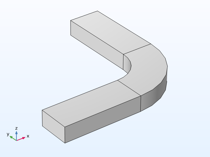 A 3D model of an h-bend waveguide.
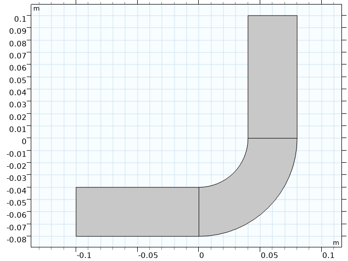 The 2D cross-sectional geometry of the h-bend model.
H 弯波导模型的三维几何(左)和二维横截面(右),物理特性使其可以在二维中进行设置和计算。
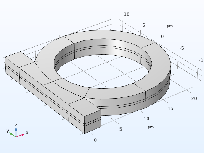 3D geometry of an optical ring resonator notch filter.
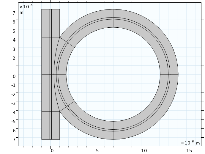 The 2D cross-sectional geometry of the optical ring resonator notch filter model.
光学环形谐振器陷波滤波器模型的三维几何(左)和二维截面几何(右)。在计算三维模型之前,二维模型用于研究其不同设计方案。
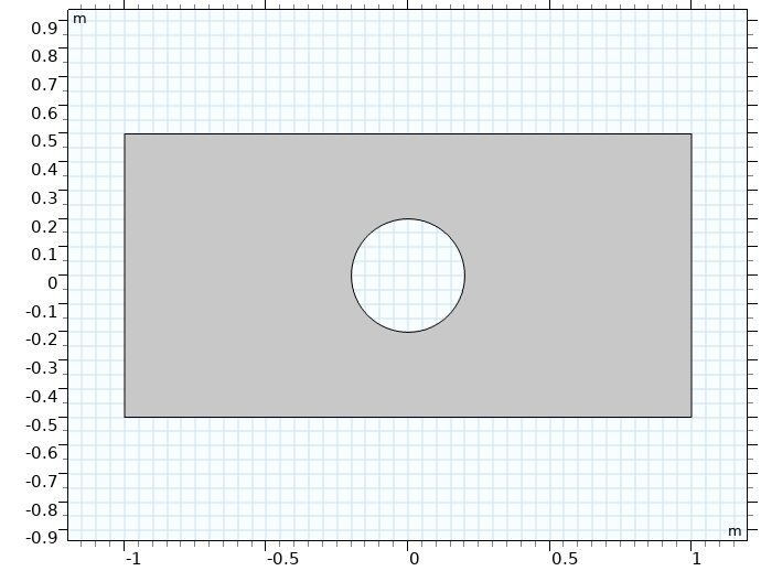 A 2D rectangular plate model with a hole in the center.
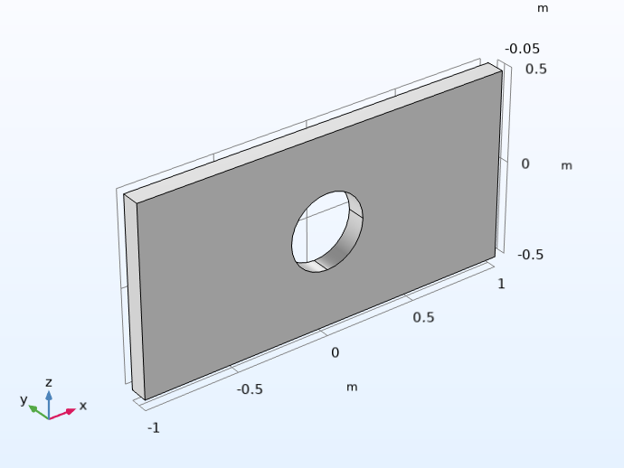 The rectangular plate model in 3D.
中心有孔的矩形板模型。在转换成完整的三维模型(右图)之前,先 使用平面应力假设对板材进行二维模拟(左图)。
使用这种方法还可以帮助开发大型或复杂的三维模型。通过尽可能利用二维模型近似,您可以在将其应用到三维模型之前更快速、更轻松地研究特定的仿真,可能包括分析任何细小或复杂的几何特征、材料属性值,以及物理场、多物理场耦合、网格或求解器等的设置。
过程
在 COMSOL Multiphysics 中,使用平面切割实体分为两个步骤。首先,为三维模型组件的几何添加一个工作平面。放置工作平面时,需要注意工作平面切割三维实体对象的位置,以获得适当的横截面。
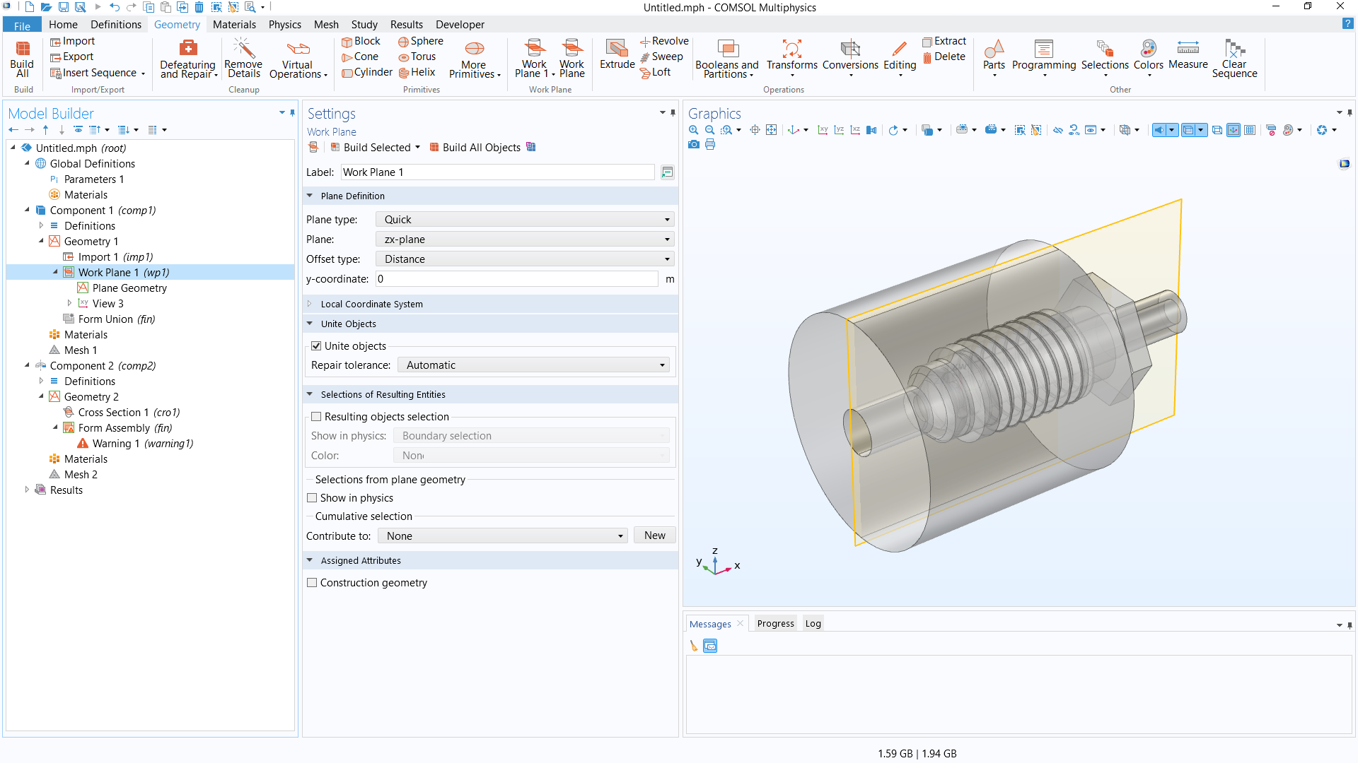 The COMSOL Multiphysics UI showing the Model Builder with the Work Plane feature selected, the corresponding Settings window, and the Graphics window with the 3D geometry of a pipe fitting model.
管件 模型的三维几何,可通过透明度查看其内部。在 xz 平面上沿设计中心添加了一个工作平面,获得其横截面。
接下来,添加第二个模型组件(二维或二维轴对称),然后添加一个 横截面 几何操作,可以由之前在三维模型组件中定义的工作平面获得所需的横截面。(您也可以使用 投影操作 来完成此操作,但请注意此功能需要使用设计模块)。
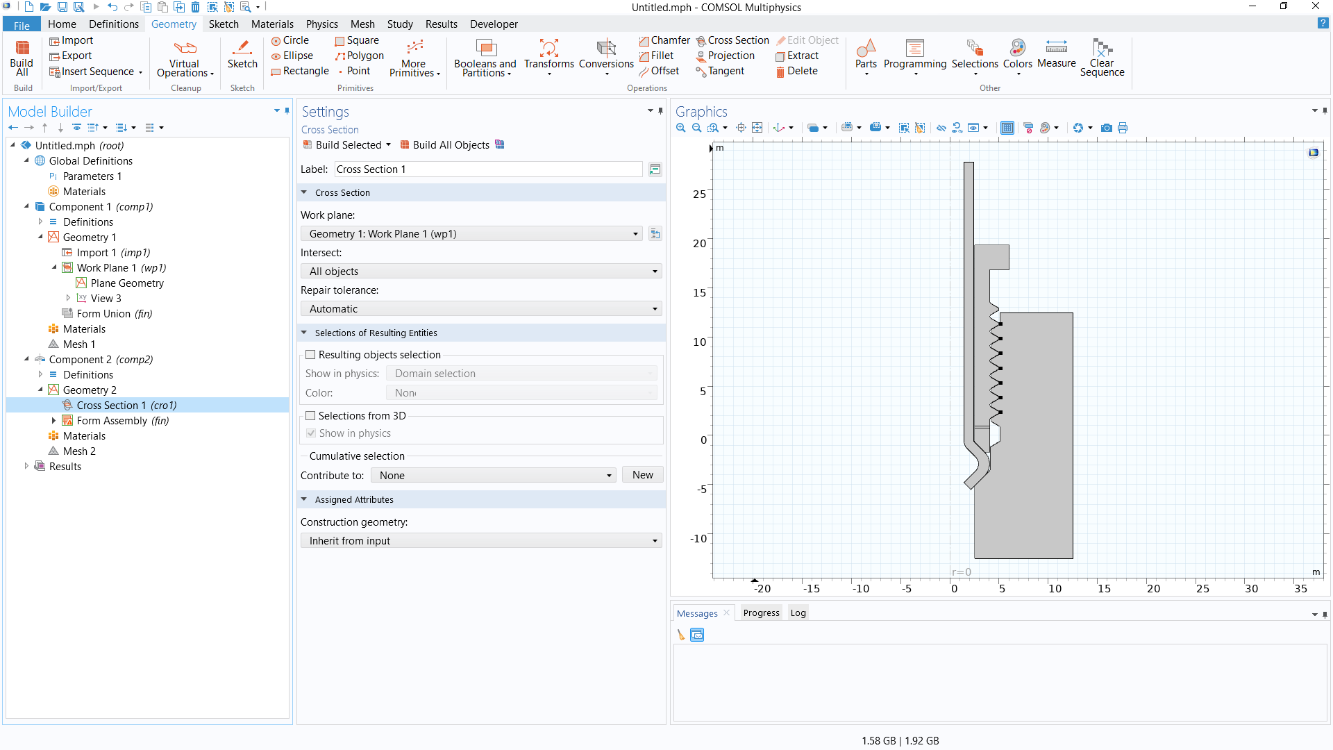 The COMSOL Multiphysics UI showing the Cross Section feature selected, the corresponding Settings window, and the Graphics window with the 2D axisymmetric geometry of the pipe fitting model.
用于创建管件二维轴对称模型的横截面。
打开软件,并使用练习文件跟随下面的视频逐步学习如何转换三维几何用于二维模型组件。我们还将讨论如何对三维几何进行必要或最优的准备,以获得适当的、有代表性的二维截面。这个过程在很大程度上取决于三维几何的设计和其中包含的特征。
教学视频:通过三维设计的横截面创建二维几何
仿真练习
请通过以下列出的后续仿真练习,对您从本文中学习的方法进行实践。文中所提供的指导有意进行了简要概括,以鼓励您自主解决问题。您可以使用文中随附的解模型文件手动检查您的模拟结果,或使用 比较工具 找出差异。
推荐练习:
- 对于 管壳式换热器 模型的几何(MPH 文件),确定如何将三维模型转换为二维模型,以获得下图所示的几何。
- 对于 波纹状圆形喇叭天线 模型几何(MPHBIN 文件),创建用于二维轴对称模型设计的几何。
- 对于 球形止回阀 模型几何(MPHBIN 文件),创建用于二维轴对称模型设计的几何。
关于管壳式换热器模型的几何,您可从上面的链接文本中下载 MPH 文件。如需 MPHBIN 文件,请先下载上面链接中的文件,然后将其导入软件。
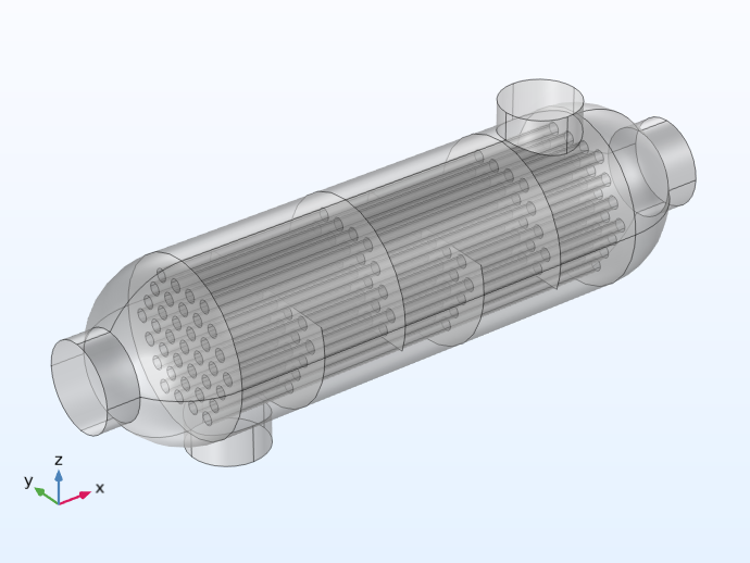 The 3D geometry of a shell-and-tube heat exchanger model.
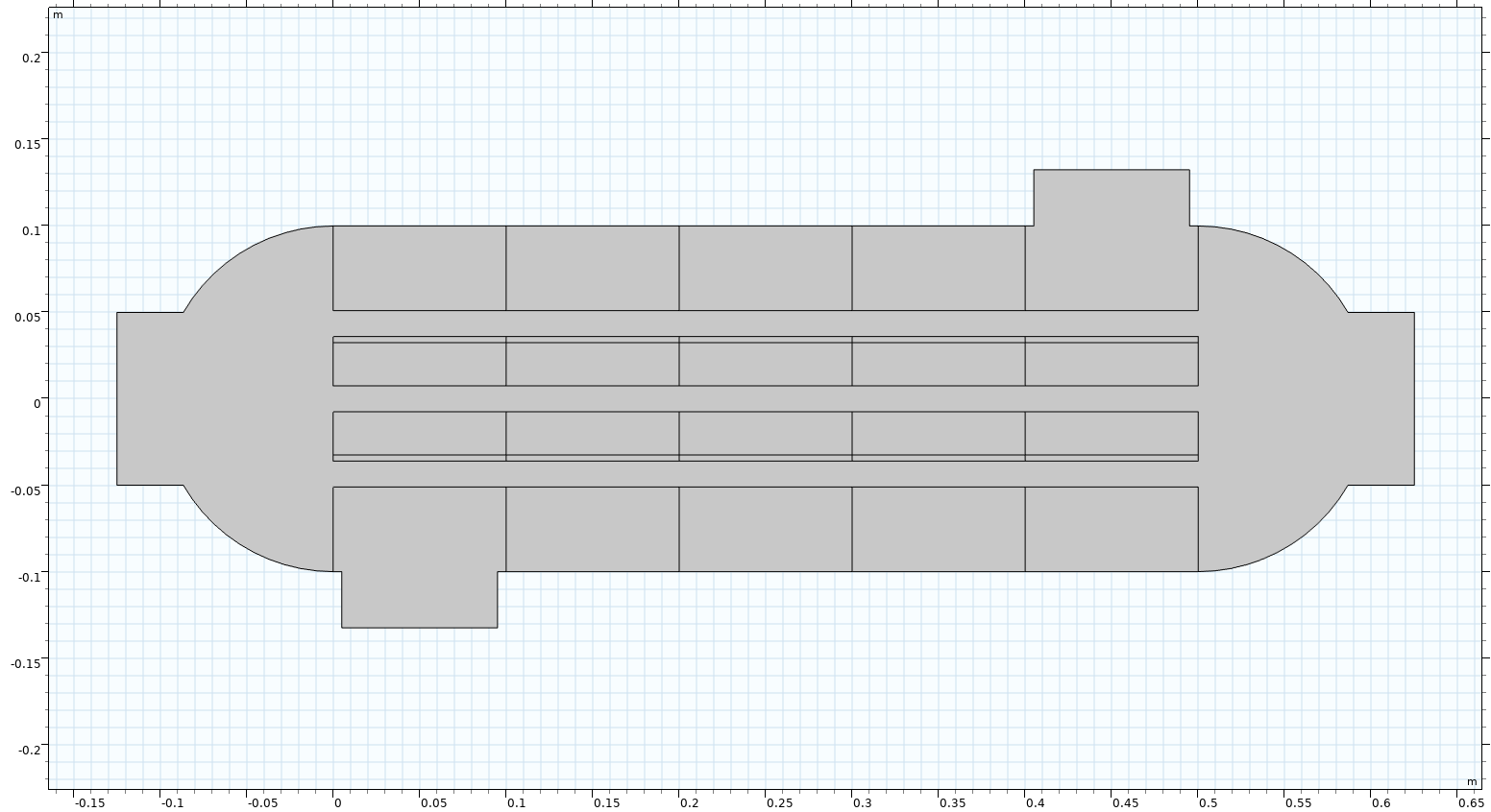 The 2D geometry of the shell-and-tube heat exchanger model.
管壳式换热器的三维模型几何(左)和用于二维模型设计的几何(右)。
进一步学习
要了解将模型几何由三维降低至二维的更多信息,请参阅学习中心的文章 “使用对称性减少模型尺寸”。在 COMSOL 案例库中,还有一些可以同时模拟二维和三维设备或系统的教学模型,您可以进一步查看这些模型,了解模型的二维近似是如何实现的。这些模型及其相应的应用领域包括:
- 薄板面外传热(传热)
- 薄域中的质量传递(化学)
- 电路板的对流冷却(流体流动)
- 永磁电机二维模型(AC/DC)
- 永磁电机三维模型(AC/DC)
- H 弯波导(射频)
- 固态装配谐振器二维(MEMS)
- 固态装配谐振器(三维)(MEMS)
请提交与此页面相关的反馈,或点击此处联系技术支持。